
converter 12 vdc to 230 vac or inverter
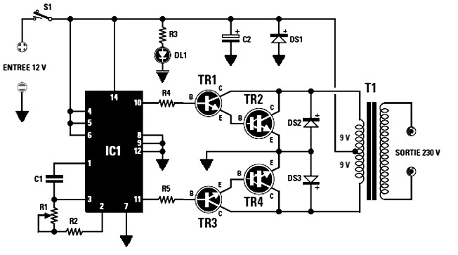
The described circuit involves a power inverter that converts a low-voltage direct current (DC) input into a high-voltage alternating current (AC) output. The transistors TR2 and TR4 play a crucial role in the switching process, facilitating the conversion by rapidly turning on and off. Proper thermal management is essential; thus, the selection of an adequately sized heatsink is critical to ensure reliable operation and prevent thermal failure of the transistors.
The transformer T1 is a vital component in this circuit, as it steps up the voltage from the secondary winding to the desired output level. The transformer’s core size directly influences the maximum power output, with the specifications indicating that a 50 VA transformer can support a secondary current of 0.2 A, while a 90 VA transformer can handle 0.4 A. The total current drawn from the inverter should be considered, as it affects the overall efficiency and thermal performance of the circuit.
When designing the inverter circuit, attention must be paid to the layout and component selection, ensuring that all parts are rated for the expected voltages and currents. The efficiency of the inverter can be optimized by selecting high-quality components and minimizing losses in the circuit. Additionally, protective measures such as fuses or circuit breakers should be included to safeguard against overcurrent conditions.
In conclusion, this power inverter circuit is a practical solution for converting 12 V DC to 230 V AC, suitable for various applications. The careful selection of transistors, transformer specifications, and thermal management strategies are essential for achieving reliable and efficient performance in the designed circuit.The two final power of TR2-TR4 should be mounted on heatsink the right size, otherwise they will overheat. You can choose from MJ4033 MJ3007 or more, provided that the NPN. The maximum power output that can be used depending on the size of the core of the transformer T1, the VA is: with 50 VA can be taken in the secondary 230 V 0.
2 A (current consumed by the end will be 4 A) with 90 VA can be taken on the secondary 230 V 0. 4 a (current consumed by the end will be 7 A). The schematic diagram come from circuit: Converter 12 Vdc to 230 Vac or Inverter power supply. Go to that page to read the explanation about above power supply related circuit diagram. 🔗 External reference
Related Circuits
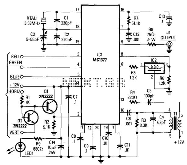
This circuit utilizes a Motorola MC1377 to generate NTSC video from an RGB source. The components are not critical, with the exception of resistor R7, which should have a tolerance of 1%, and capacitor CB, which should have a...
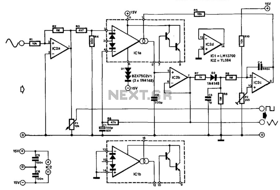
Many function generators utilize a rectangular waveform generator that comprises a Schmitt trigger and an integrator. The triangular signal generated by the integrator is subsequently transformed into a sinusoidal signal using a diode network. The converter described here operates...
The TLD 5085EJ is a smart LED buck converter featuring an integrated power switch, designed to drive a load current of up to 1.8A with excellent line and load regulation. This device is specifically intended for stepping down input...

This power converter is utilized in the LHC machine to supply power to superconducting magnets. It is situated within the underground installation of the LHC, positioned close to the loads to minimize cable losses. The converter operates at a...
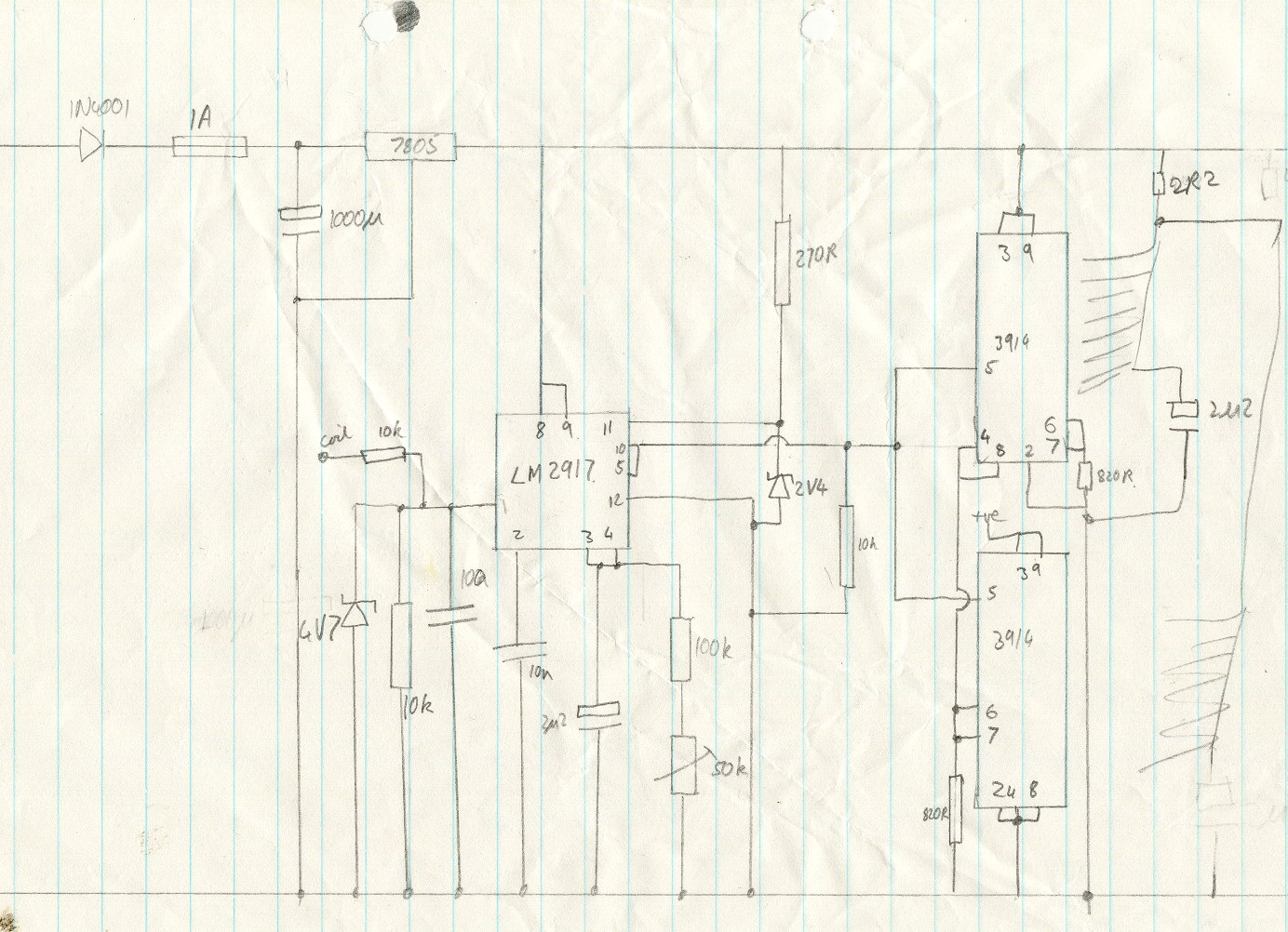
This circuit utilizes an LM2917 frequency-to-voltage converter. The input is connected to the low voltage side of the ignition coil, with various components designed to produce a full-scale output at 6000 RPM, corresponding to 12000 ignition pulses per minute,...
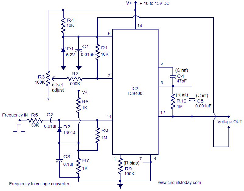
A simple and low-cost frequency-to-voltage converter based on the TC9400 IC from Microchip is presented. The TC9400 can be configured as either a voltage-to-frequency converter or a frequency-to-voltage converter, requiring minimal external components. The internal functional blocks of the...
Warning: include(partials/cookie-banner.php): Failed to open stream: Permission denied in /var/www/html/nextgr/view-circuit.php on line 713
Warning: include(): Failed opening 'partials/cookie-banner.php' for inclusion (include_path='.:/usr/share/php') in /var/www/html/nextgr/view-circuit.php on line 713