
converter lhc4 6 8ka 08v

The power converter's architecture is designed to ensure reliability and efficiency in demanding conditions. The modular approach allows for scalability, enabling the addition or replacement of power modules as needed without significant system downtime. The water-cooling system is critical for maintaining optimal operating temperatures, especially in the dense environment of the underground installation. The use of high-frequency switching technology minimizes energy losses and enhances overall efficiency. The integration of advanced diagnostic capabilities ensures that any potential issues can be identified and addressed promptly, reducing the risk of equipment failure. The combination of active redundancy and sophisticated control mechanisms underscores the commitment to safety and reliability in the operation of superconducting magnets, which are vital for the LHC's functionality. The design philosophy prioritizes not only operational efficiency but also the safety of the equipment and personnel involved in the particle acceleration processes.This Power Converter is used in LHC Machine to power superconductive magnets. It is located in the LHC underground installation, close to the loads to limit cable losses in the underground installation. A high current high frequency (25 kHz) switch mode power converter, designed for powering of superconducting loads requiring only positive current
and positive voltage control (1 quadrant). Constructed from a modular architecture composed of 2kA power modules, the system can be easily adapted to suit specific powering requirements. Used extensively in the LHC particle accelerator. The converter is water cooled, and is thus ideally suited to situations where air losses must be carefully managed.
Designed for underground operation, extensive remote diagnostics have been foreseen to allow efficient monitoring and fault diagnostics without requiring being present locally. Power Converter is normally assembled using a n+1 Power Bricks [+2kA +08V] to provide active redundancy in case of one subconverter is lost.
For example, a [+8kA +08V] is composed of 5x [+2kA +08V] Power Brick, working as current source being controlled by a Voltage Source main control. Power Brick is actually a high frequency current source (7-8kHz) controlled by a 1kHz bandwidth voltage loop.
One can notice that Power Brick is actually a current cource in its structure, even if voltage source capacitors are located in this block for mechanical reasons. Representation below gives a symbolic structure of the power converter, clarifying the cascade loops.
( Is1 & Is2 are actually assumed to be representative and equal to the current of each power transformer secondaries). The multiplication of rectifier stages in each output module gives the following advantages: easier design of magnetic parts, lower rating fuse (lower losses) to protect whole Power Converter being short-circuited by a faulty secondary (fuse would immediately blow in case one of the schottky dies, giving the possibility to the whole power converter to reconfigure the current level in other current sources to maintain required voltage level).
High precision current control loop is managed by the digital controller called FGC (Function Generator Controller). This unit includes a high precision Sigma Delta Analog to Digital Converter which digitalize the analog current measurement coming from 2 DCCTs (DC current Transducer).
Precision is then directly relying on sensor precision: DCCT, the ADCs, and the algorithm being used for the regulation loop. Voltage source is then used as a power amplifier, powering the load through a high bandwidth voltage loop (>500Hz).
Power Converter is part of magnet protection scheme, even if not directly fully responsible of the monitoring and diagnostic of the superconductive magnet status. Dedicated systems QPS (Quench Protection System) + PIC (Power Interlock Controller) can interlock Power Converter if magnet safety requires it.
Always ensure that external protection system can stop the Power Converter through a safe signal called Fast Abort. This redundant signal uses 2 paths to interlock and stop the converter and its redundancy is checked each time it acts.
It directly acts on AC Contactor bobbin, ensuring its opening as required. Stop powering the load in safe way (handling the magnet energy even when stopping, through dedicated system called Free Wheeling Diode Safe Paths). This passive system based on different paths using several free-wheeling diodes in the rack provide a safe discharge path for magnet current (energy).
The system is based on 3 different paths provided by Free-Wheeling Diodes providing a safe path for magnet current. The number of Free-Wheeling diodes (x40. x80, 20x per cards) to be considered depends on the converter type (see chapter Machine Installation below).
Only one unique Additionnal Free-Wheeling Diode is always present as a last chance 3rd path. The circuit injects a 10 🔗 External reference
Related Circuits
The lack of compensation facilitates the processes of development and testing. The figure of 6 billion frequently appears as the estimated number of cell phones in use globally. Published estimates indicate an average. The discussion of compensation in electronic circuits...
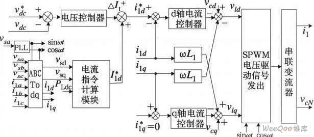
The demand for high-quality electric energy in modern industrial development is increasing, making it essential to provide safe and reliable green power to energy consumers. Uninterruptible Power Supplies (UPS) are crucial for improving electric energy quality and ensuring the...
This circuit was designed to provide a 5 V output from a 24 V battery of a solar-powered generator. While solar power is essentially free, it is crucial to avoid waste, especially in small installations; if the battery depletes...
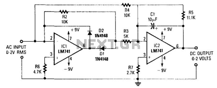
A DC level is generated that corresponds to the AC input RMS value (for a sine wave). The gain of the integrated circuit (IC) is set to a factor of 2 to 1.11. This factor represents the average-to-RMS conversion...
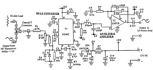
Any mode (e.g., CW, AM, SSB, FSK) initiated in the HF transmitter or transceiver can be regenerated at LF (100 to 200 kHz) using this simple converter. The LF output can drive an LF Power Amplifier. The February 2000...

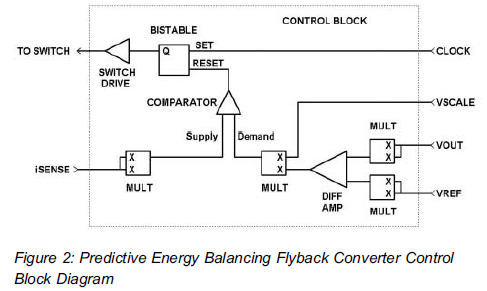
The transition from diodes to synchronous-rectification (SR) MOSFETs in the secondary circuits of flyback converters is increasing with each new generation of MOSFETs, enhancing performance with minimal or no cost increase. SR MOSFETs can offer improved efficiency compared to...
Warning: include(partials/cookie-banner.php): Failed to open stream: Permission denied in /var/www/html/nextgr/view-circuit.php on line 713
Warning: include(): Failed opening 'partials/cookie-banner.php' for inclusion (include_path='.:/usr/share/php') in /var/www/html/nextgr/view-circuit.php on line 713