
Conveyor control Ladder
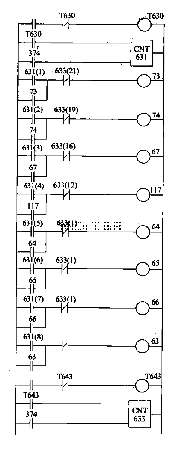
The described circuit employs a drum controller for sequential control of equipment in a sand production line, utilizing pulse counting mechanisms to manage operational states effectively. The primary components include timers T630 and T643, which generate pulses at regular intervals, specifically every 5 seconds. The drum controller, comprising capacitors C631 and C633, counts these pulses to determine the operational sequence of the equipment.
In the operational phase, when the start signal is received, T630 initiates pulse generation. Each pulse advances the drum controller (C631), causing the associated normally open contacts to close, which starts the machinery in a predetermined sequence. This ensures that each piece of equipment is activated in the correct order, optimizing the production flow and preventing operational overlaps that could lead to inefficiencies or equipment damage.
Conversely, when a stop signal is activated, T633 takes over to control the stopping sequence. It generates pulses in a similar manner, advancing C633. Upon reaching a specified count, the drum controller closes the normally closed contacts, which halts the operation of the equipment. This method of control allows for precise timing and coordination among the different components of the production line, ensuring safety and efficiency.
The integration of a programmable logic controller (PLC) within this design enhances the system's flexibility and adaptability. The PLC can be programmed with various instructions tailored to specific operational needs, allowing for adjustments in the timing, sequence, and conditions under which equipment operates. This capability is particularly beneficial in environments where production requirements may change frequently, providing a dynamic solution to automation challenges.
Overall, the schematic design exemplifies a robust approach to automation in material handling and production processes, demonstrating the effectiveness of using a drum controller in conjunction with PLC technology for real-time operational management.According to the characteristics of the system, using the drum controller to achieve the above requirements, the design of the ladder as shown in FIG. As follows: 1) C631, C633 as a drum controller, which counts pulses generated by the T630, the pulse period is sequentially stopped at 5s C633. Use, its counting pulses generated by the T643, the pulse period is 5s. 2) after the start signal is active. T630 produces a pulse every 5s, C631 step, the corresponding pair of normally open contacts closed, the equipment along the sequence start.
3) After the stop signal is active, T633 produces a pulse every 5s, C633 step, and when it reaches the appropriate time, a corresponding pair of normally closed contacts closed, the equipment order to stop. (4) Conclusion In this case sand production line automatic control, for example, according to transport sand, sand and grind roller conveyor system flow characteristics, were used for the timer, drum controller, a shift register sequence control ladder the design of.
As can be seen, PLC in order to control side surfaces powerful, has a wealth of programming instructions, user program design flexible, convenient and very suitable delivery systems such as automation and control production lines.
Related Circuits
A 567 IC tone decoder/detector can be utilized to construct a remote control or intercom system. This circuit is capable of controlling a relay or transmitting an audio signal. The 567 IC is a versatile integrated circuit designed for tone...
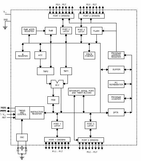
A microcontroller (MCU) is a compact computer integrated into a single circuit, comprising a relatively simple CPU along with supporting functions such as crystal oscillators, timers, sensors, and serial and analog input/output (I/O). Microcontrollers are designed for small-scale applications,...

Most homes today have at least a few infrared remote controls, whether for the television, video recorder, stereo, etc. Despite this, many people have experienced frustration with lights that remain on after settling into a comfortable chair to watch...
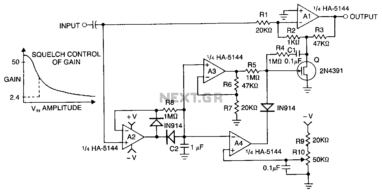
Automatic gain control (AGC) is a valuable feature found in various audio amplifier circuits, including tape recorders, telephone speakerphones, communication systems, and public address (PA) systems. This circuit utilizes a HA-5144 quad operational amplifier (op-amp) and a field-effect transistor...
Faulty readings from the DS18B20 temperature sensors used in tank thermometers were likely caused by the waterproofing method involving heat shrink and silicone. This situation provided an opportunity to enhance the code for better tolerance against erroneous readings. The...
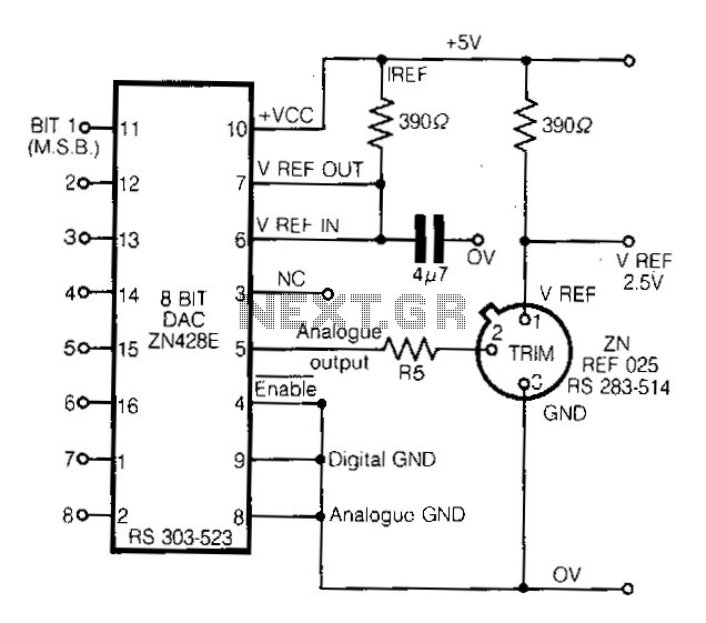
This circuit demonstrates a straightforward approach to achieving a voltage reference that can be adjusted using an 8-bit Digital-to-Analog Converter (DAC) equipped with an integrated voltage reference. The analog output from the DAC controls the trim pin of the...