
Cool gradually dimming light switches

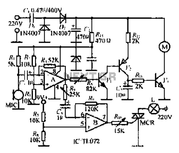
The lighting circuit described utilizes a fade dimming control mechanism, which allows for gradual adjustment of brightness in lighting applications. The circuit is designed around two transistors, VT1 and VT2, which serve as the primary control elements for the dimming functionality. These transistors are configured to operate in a linear region, allowing for smooth transitions in light intensity.
The inclusion of RC components in the circuit plays a critical role in determining the fade rate. The resistor-capacitor (RC) network introduces a time delay that affects how quickly the lighting fades in or out, thereby enhancing user experience by providing a soft start and stop to the illumination.
Furthermore, the circuit employs a full-wave bridge rectifier composed of four diodes (VD1 to VD4). This configuration is essential for converting the incoming 220V AC supply into a pulsating DC voltage. The bridge rectifier ensures that both halves of the AC waveform are utilized, resulting in a more efficient power conversion. The output from the rectifier is then smoothed by additional filtering components, if present, to provide a stable DC voltage suitable for the operation of the transistors and the overall dimming circuit.
Overall, the design of this fade lighting circuit is aimed at providing a user-friendly interface for controlling light levels while ensuring reliable performance and efficient power management. The careful selection of components and their arrangement in the circuit are crucial for achieving the desired dimming effects and maintaining the integrity of the lighting system.Fade fades the lighting circuit switch shown in Figure 1-12. The figure for the light switch S, H is accused of lighting. Transistor VT1, VT2 and RC components fade dimming con trol circuit. Since transistor VTl, V12 must work in DC like state, the circuit and the other with four diodes VDl ~ VD4 bridge rectifier circuit composed of the full-wave DC 220V AC into pulsating voltage supply road work use.
Related Circuits
This project involves a simple light-activated police siren utilizing a light-dependent resistor (LDR) and an NE555 timer. It is advisable to complete some preliminary projects before attempting this one. The NE555 timer, configured in slow astable mode with a...
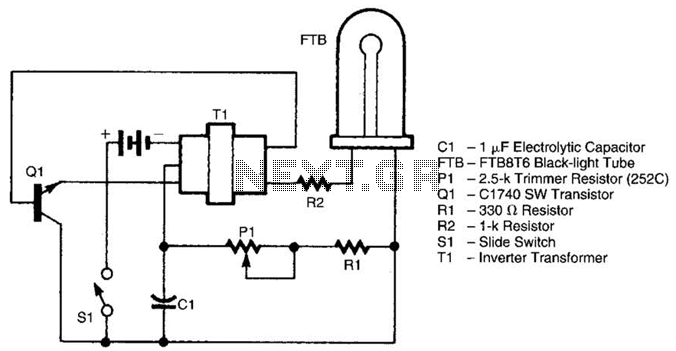
The battery-operated black light utilizes a U-shaped, unfiltered black-light tube, which requires approximately 250 Vac for operation. To generate the 250 Vac from a 6-V battery, the circuit employs a one-transistor blocking oscillator that drives a ferrite inverter transformer....
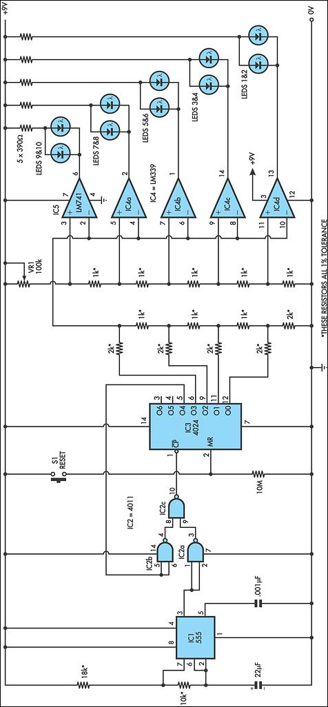
This circuit replicates the starting light sequence used by FISA in Formula One racing. It can be utilized with slot car sets (such as HO scale AFX, Life Like, or Tyco sets) or radio-controlled cars. The circuit employs a...
A microphone (MIC) is used to capture sound, which is then converted into a voltage signal. An operational amplifier (op-amp A) acts as a buffer; one output is directed to a motor drive circuit to control the motor's rotation...
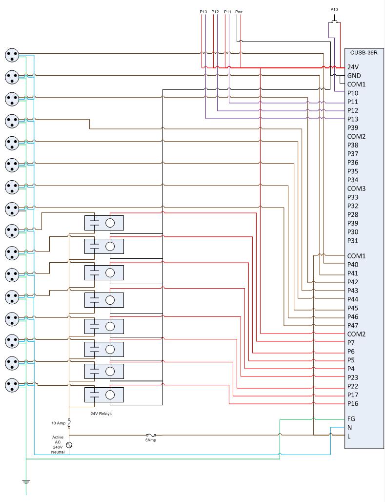
This is the circuit diagram for the Comfile CUSB-36R Programmed Christmas Lights. If it is difficult to read, please contact me via email at [email protected], and I will provide a more detailed schematic. The Comfile CUSB-36R can either drive...

This is a light sensor circuit designed to detect darkness, utilizing the op-amp 741 integrated circuit as the primary control element. The circuit is straightforward and specifically designed to sense light during nighttime. The light detection is accomplished using...