
light activated police siren using 555 timer
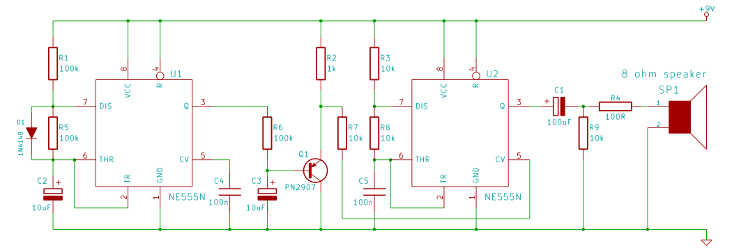
The light-activated police siren circuit employs two NE555 timers, each configured in astable mode to generate different frequency outputs. The first timer (timer1) operates at a slower frequency due to its higher resistance value (R1 = 68K), while the second timer (timer2) operates at a faster frequency with a lower resistance (R4 = 10K). The interaction between these two timers is crucial for producing the desired siren effect, as timer1 influences the frequency modulation of timer2.
The control voltage applied to pin 5 of timer2 plays a significant role in determining the output frequency. By adjusting this control voltage, the user can achieve a range of output frequencies, which can be fine-tuned to create a more realistic siren sound. The circuit's sensitivity to light is governed by the LDR, which changes its resistance based on the ambient light levels. When light strikes the LDR, it allows current to flow, activating the circuit through the transistor Q1, which acts as a switch.
Furthermore, the variable resistor (VR1) provides an adjustable sensitivity setting. By changing the resistance value of VR1, the threshold at which the LDR activates the circuit can be modified, allowing for customization based on environmental conditions or specific user requirements. If the roles of the LDR and VR1 are reversed, the circuit's functionality will invert, demonstrating the flexibility of the design.
In summary, this light-activated police siren circuit integrates two NE555 timers in astable mode, utilizing a light-dependent resistor and a variable resistor to create an adjustable, light-sensitive output that mimics a police siren. The design emphasizes the importance of component values and configurations in achieving the desired frequency modulation and overall functionality.Here`s a simple light activated police siren using light dependent resistor and NE555 timer. Before you make this project, I would recommend you to make the following projects. The 555 timer with R1=68K(say timer1) is configured in slow astable mode and the timer with R4=10K(say timer2) is configured in fast astable mode. By applying voltage to t he Pin 5 (control voltage input), we can change the timing characteristics of the timer. In the astable mode, control voltage can vary from 1. 7V to the input voltage level(i. e. 6V in this case) that produces output frequency lower or higher than the frequency produced by the network of R1, R2 and C1 for timer1 and R4, R5 and C3 for timer2. To know more about the output frequency of 555 timer, read this tutorial: ASTABLE MODE The police siren effect is produced because of the input voltage at pin 5 of timer2.
It makes the timer2 to produce frequency modulated output. In this circuit, timer1 controls the output frequency of timer2, producing police siren effect. When you put light on LDR, the police siren circuit gets power from the transistor Q1. You can change the sensitivity of the circuit by varying the resistance VR1. If you swap LDR and VR1, the circuit works in opposite way. HOW TO MAKE A LIGHT SENSOR 🔗 External reference
Related Circuits
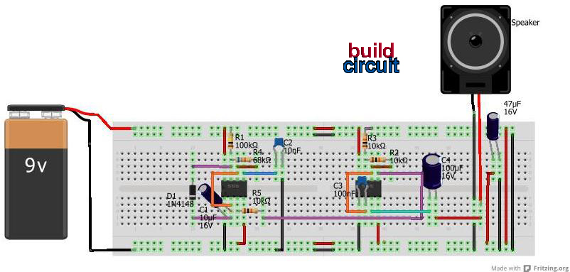
This tutorial outlines the construction of a wailing siren that produces a tone with varying pitch. The circuit incorporates two 555 integrated circuits (ICs) and a loudspeaker. The wailing siren circuit is designed to create an audio effect that simulates...

In this circuit, a 4017 CMOS decade counter can be utilized to construct a timer circuit. The push-button S1 will discharge capacitor C1 through resistor R2. The 4017 CMOS decade counter is a versatile integrated circuit that can count from...
This clock timer utilizes a PIC16F628 microcontroller to display a 3.5-digit time format and control an external load. It is programmable to time intervals from 1 to 59 minutes. The clock features a calendar that accounts for leap years...

The sound produced imitates the rise and fall of an American police siren. When first switched on, the 10 µF capacitor is discharged, and both transistors are off. When the push button switch is pressed, the 10 µF capacitor...

Figure 282 illustrates a simple emergency lamp circuit designed to activate during a power outage. The circuit utilizes a transformer (T) for voltage stepping, diodes (VD1 to VD4) for rectification, and a capacitor (C) for smoothing the output. During...
This handy little circuit can tell the difference between darkness and light, making it very useful for switching on and off signs, porch lights or other things when it gets dark or light. More: R1 Adjusts sensitivity The circuit described...