
Cosine wave Oscillator
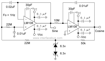
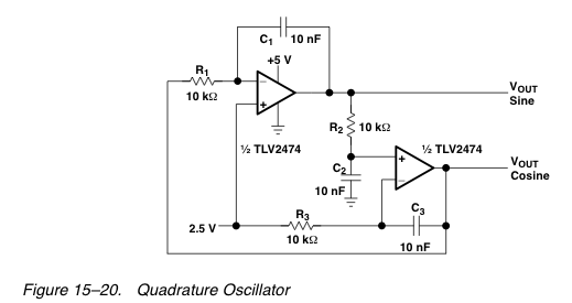
This circuit consists of two operational amplifiers configured to generate sine and cosine waveforms. The first operational amplifier (op-amp) operates in a sine wave configuration, utilizing feedback components that establish the desired frequency of 1Hz. The output of this op-amp is a pure sine wave signal. The second op-amp is configured to generate a cosine wave, which is essentially a sine wave phase-shifted by 90 degrees. This is achieved by applying the sine wave output from the first op-amp as the input to the second op-amp, which processes the signal to produce the cosine output.
The zener diodes included in the circuit serve as voltage reference components that help maintain stable output levels by setting the minimum and maximum voltage thresholds for the op-amps. This is crucial for ensuring that the output signals remain within desired limits and do not exceed operational parameters, which could lead to signal distortion or damage to the components.
The LM108 operational amplifier is a versatile component widely used in various applications. Its compatibility with numerous package styles allows for flexibility in circuit design and integration. When substituting operational amplifiers, it is essential to consider the specifications and performance characteristics of the replacement components to ensure they meet the requirements of the circuit.
In summary, this circuit effectively demonstrates the generation of sine and cosine waveforms using operational amplifiers, showcasing the functionality of phase shifting and voltage regulation through the use of zener diodes. The careful selection of components and their configurations is critical for achieving the desired output characteristics.This circuit is designed to output both a sine wave and cosine wave. This particular design uses an operational amplifier. As shown in the schematic the output frequency is set by the component values as 1Hz. The first operational amplifier outputs a 1Hz sine wave while the second operation amplifier outputs a 1Hz cosine wave. The circuit outputs two sine wave, one 90 degrees out of phase with the other. The two zener diodes are used to set the minimum and maximum voltages. Refer to the link for another Op Amp Sinewave Generator, with a single output. Of course the primary function of the first op amp is to produce a sine wave, while the second op amp produces the same signal but 90 degrees phase shifted. That is the second op amp uses the sine wave as an input and outputs that signal out of phase [phase shifter].
The operational amplifier is a general purpose device, and may be substituted as required. However many of the passive parts set the frequency of operation and should not be substituted, unless a new output frequency is required. Op Amp: A LM108, general purpose operational amplifier. The most common package style was an 8-pin or 16-pin Plastic DIP Package, or Ceramic DIP Package [military and space applications], an 8-Lead TO-5 Case or a surface mount SOIC Package.
List of Companies making Operational Amplifier ICs. There is an upgrade which may still be stocked as LM108A, although many different op-amps might be substituted for the one in the schematic. Zener Diode: Reference diode, labeled as 6. 3 volts [Vz]. A 6. 2v 1N4460 is referenced on this site [5. 89v minimum to 6. 51v maximum]. Case style is a DO41 Package [Through-Hole]. 🔗 External reference
Related Circuits
The objective is to design a square-wave generator with an output range of 0 to +5V. Additionally, the design should allow for the modification of the signal to enable adjustment of the duty cycle of the pulse (PWM). The square-wave...
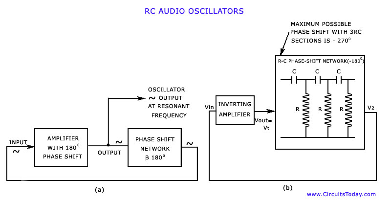
The discussion has focused on oscillators that utilize L-C tuned circuits, which create a 180° phase shift due to inductive or capacitive coupling, in addition to another 180° phase shift produced by the transistor itself. These L-C oscillators are...
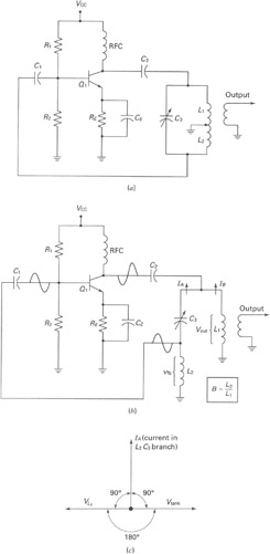
A widely recognized circuit is the Hartley oscillator, which is characterized by a tapped coil within the LC tank circuit. The tap point of the coil is grounded. The oscillator's amplifier section functions as a common-emitter amplifier, resulting in...
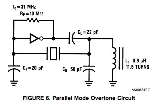
With the advent of high speed HCMOS circuits, it is possible to build systems with clock rates of greater than 30 MHz. The familiar gate oscillator circuits used at low frequencies work well at higher frequencies and either LC...
After disappointing results with a transformer-based component tester, there is an interest in generating a ±10 V sine wave at approximately 50 Hz using minimal components. While an ATmega microcontroller could achieve this, it may be considered excessive, requiring...
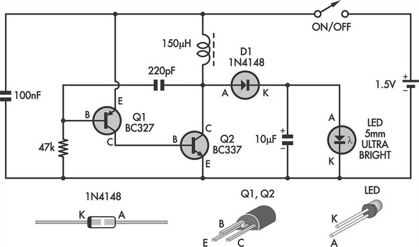
This simple LED torch is driven by a 2-transistor blocking oscillator that steps up the voltage from a 1.5V cell. It relies on the inherent current limiting of the 150 µH choke to protect the white LED from overdrive....