
RF OSCILLATOR CIRCUITS

The Hartley oscillator is a type of LC oscillator that utilizes an inductor-capacitor (LC) tank circuit to generate oscillations. The key component of this circuit is the tapped inductor, which allows for the division of inductance into two parts, L1 and L2. The configuration of the inductor and capacitor determines the frequency of oscillation. The oscillator operates based on the principle of positive feedback, where a portion of the output is fed back to the input to sustain the oscillations.
In this configuration, the common-emitter amplifier plays a crucial role in amplifying the signal. The grounding of the tap point in the inductor ensures that the phase relationship between the input and output signals is maintained correctly. The requirement for the feedback network to provide an additional 180-degree phase shift is essential for the system to oscillate, as it ensures that the feedback voltage reinforces the input signal.
The resonant frequency of the tank circuit is determined by the values of L1, L2, and C3. At this frequency, the reactance of the capacitive branch (L2-C3) effectively cancels out the inductive reactance of L1, resulting in a condition where the circuit can sustain oscillations. This balance between inductive and capacitive reactance is critical for the stability and performance of the oscillator.
Mathematically, the relationship governing the oscillation frequency can be expressed as follows:
f = 1 / (2π√(L_total * C_total))
Where L_total is the equivalent inductance of the parallel combination of L1 and L2, and C_total is the capacitance of C3. Understanding this relationship is fundamental for designing and analyzing Hartley oscillators in various applications, including signal generation and frequency synthesis.A popular circuit known as a Hartley oscillator. Its identifiable feature is the tapped coil in the LC tank circuit. Notice that the coil`s tap point is grounded. The amplifier portion of the oscillator is a common-emitter amplifier. Therefore, the ac base voltage and ac collector voltage are 180 out of phase. This means that the feedback network must provide an additional 180 phase shift so that the feedback voltage is of the correct phase to sustain oscillations. To help you understand the circuit`s operation, it has been redrawn in Fig. 2-2( b). Notice that L 1 is in parallel with L 2 and C 3 in series. At the resonant frequency of the tank circuit, the net reactance of the L 2 C 3 branch appears capacitive. Also, the net capacitive reactance of the L 2 C 3 branch equals the inductive reactance of the L 1 branch.
This gives us the following mathematical relationship. 🔗 External reference
Related Circuits

Below 10 MHz, the development of engineering models is relatively straightforward and not significantly influenced by printed circuit board layout. In the VHF range, parasitic circuit elements and unwanted coupling can severely impact efforts to achieve cost-effective performance without...
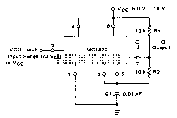
The VCO circuit, which has a nonlinear transfer characteristic, will operate satisfactorily up to 200 kHz. The VCO input range is effective from V% Vcc to Vcc - 2 V, with the highest control voltage producing the lowest output...
This article compares high-side and low-side amplifiers used for measuring battery charging currents. It recommends selection criteria for current-sense resistors and describes a high-voltage circuit breaker designed for overcurrent protection. High-side and low-side amplifiers are essential components in battery management...
A PLL oscillator, or phase-locked loop oscillator, is a control method that compares a controlled system or plant to a reference signal. A phase-locked loop (PLL) oscillator is a sophisticated electronic circuit designed to synchronize an output signal's phase and...
The objective is to test a Wien bridge oscillator and ensure its proper functionality. There is a study of relevant material, but some concepts remain unclear. The Wien bridge oscillator is a type of electronic oscillator that generates sine waves....
This weblog focuses on electronic circuit schematics, PCB design, DIY kits, and diagrams for various electronic projects. It features a mixer that demonstrates how to create microphone pre-amplifiers suitable for both low and high impedance microphones. The design utilizes...