
Coupler Crystal Radio
The two-circuit tuner circuit design effectively demonstrates the principles of selectivity and sensitivity in radio reception. The architecture allows for fine-tuning through the use of variable capacitors and multiple taps on each coil, enhancing the user's ability to isolate specific frequencies. The use of ABS pipe for coil construction ensures durability while maintaining a lightweight structure. The choice of 22-gauge magnet wire is appropriate for minimizing resistance and ensuring efficient signal transfer.
The mechanical arrangement of the slider device for the secondary coil is a notable feature, promoting ease of adjustment and precision in tuning. The horizontal screw mechanism allows for incremental adjustments, which are critical for achieving optimal reception. The design encourages the user to engage with the tuning process actively, fostering a deeper understanding of radio frequency manipulation.
Furthermore, the inclusion of locking nuts for the lead screw enhances operational stability, preventing unintended movement during adjustments. The overall layout of the circuit, including the strategic placement of components and the systematic arrangement of taps, reflects a thoughtful approach to circuit design that prioritizes functionality and user experience.
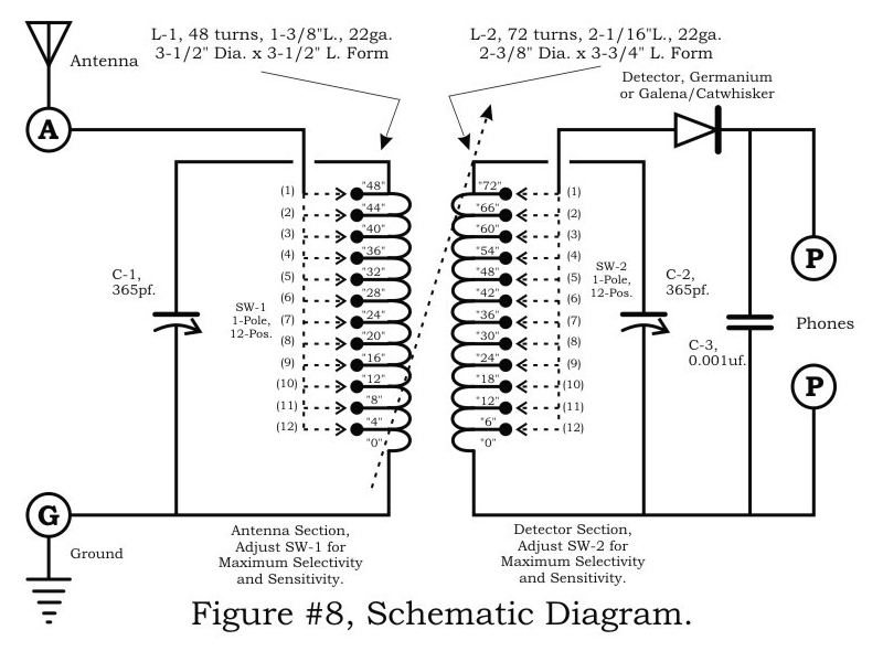
In practical application, the tuner is versatile enough to be integrated into various radio sets or used independently, making it a valuable tool for amateur radio enthusiasts and professionals alike. The detailed instructions for assembly and testing provide a comprehensive guide for users, ensuring successful implementation and operation of the circuit. This design exemplifies the balance between complexity and usability, making it an exemplary model in the field of radio engineering.A two-circuit tuner, as the loose coupler, is one of the only ways selectivity can be accomplished without sacrificing sensitivity. Let`s look at the circuit, see figure #8: The signal is introduced to the primary antenna section via SW-1 arrangement, in which the antenna can be matched to the circuit with 12 taps on Coil L-1.
Coil L-1 is also tuned with the 365 variable across the entire L-1, which is a stationery coil. The secondary detector section, L-2 is a moving coil designed to slide in and out of the primary coil. See Figure #1 & #2 and you`ll note that the secondary coil is mechanically arranged on a slider device, which is moved by a horizontal screw arrangement.
The coil L-2 is also tuned by another 365 variable and another 12 taps to the detector/phones section. To summarize: The two tuned coils with 12 taps each and the variable coupling ability, give this receiver an extreme versatility in it`s ability to separate stations.
Winding and constructing the coils is quite time consuming and important to be correct. The primary, L-1 is wound on a 3 I. D. x 3-1/2 piece of ABS pipe. The 12 taps are every 4th. Turn and are on the inside of the coil. Leave the tap wires long enough to terminate to the rotary switch, which mounts at the end of the coil. I secured the taps, toward the switch-end of the coil with hot glue. It is important that the taps run along the wall of the inside of the coil form, to minimize interference with L-2 sliding in-and-out.
Make certain that both coils are wound in the same direction and that the ground-end matches each coil arrangement. L-2 is wound on a 2 I. D. x 3-3/4 piece of ABS pipe and constructed in the same manner as L-1. Each coil is wound with 22-gauge magnet wire and divides the taps points equally, for each coil. See figure`s # 1 through 4, which illustrates the mechanics of the coil/slider assembly. This assembly can be used independently of the entire set if you desire to use on another set, or simply for an antenna tuner.
I thought the lead-screw for moving the secondary was a nice twist and when testing the set, found it to be useful as this setting can be quite critical, at times. The handle on the lead-screw is a wooden toy wheel with an axle pin for the crank handle. The two nuts that secure the lead-screw under the primary coil should be locking nuts and adjusted sot the screw moves freely.
Testing the circuit: Connect a good antenna and ground, set the switches at position #6 and move the secondary towards the primary so it is just beginning to move inside. Connect a good set of phones to the phones terminals and use your best diode for the detector. Set the antenna variable to mid-range and slowly rote the detector tuning, denoting the stations heard.
Moving the secondary coil further into the secondary will increase the volume and decrease the sensitivity. The detector-select switch will increase the volume towards #1 and decrease toward #12. The same applies to the antenna switch and practice will show the best settings for your antenna/ground and area situations.
Have Fun, and until next time! Mike. 🔗 External reference
Related Circuits

The SI2171 is a sub-package of the SI2170. For further details, please refer to the SI2170 description. The datasheet for the SI2171 can be downloaded from the link provided below. By Silicon Laboratories. The SI2171 is a versatile integrated circuit...
A circuit diagram of the T1 is a low-impedance output transformer, featuring a 5000-8 ohm resistor. The T1 low-impedance output transformer is designed to match the output of audio amplifiers to the impedance of loudspeakers, ensuring optimal power transfer and...
When the SDA (Serial Data) and SDA' lines are at a logical '1', the circuit is inactive, preventing the optocouplers IC1 and IC2 from transmitting any information. However, once the SDA line transitions to '0', the LED in IC1...

Volvo S40 Wiring Diagram Radio 1997 Manual PDF Download. The Volvo S40 wiring diagram for the radio from the 1997 model year provides a detailed schematic representation of the electrical connections and components involved in the vehicle's audio system. This...
The following circuit illustrates the SCR BRY35 used in a simple radio control circuit. Features include a straightforward and efficient receiver for operation. The SCR BRY35 is a silicon-controlled rectifier designed to facilitate the control of high-power loads through low-power...

In the current era, various technologies are emerging at a rapid pace, with new innovations appearing approximately every three months. Among these advancements is the concept of a car radio that operates without an external antenna, inspired by the...