
SCR BRY35 For Simple Radio Control Circuit
The SCR BRY35 is a silicon-controlled rectifier designed to facilitate the control of high-power loads through low-power signals. In the context of a simple radio control circuit, the SCR functions as a switch that can be triggered by a radio frequency signal, allowing for wireless control of devices.
The circuit typically consists of a radio receiver module that receives signals from a transmitter. The output from the receiver is connected to the gate of the SCR, which allows it to turn on when a specific signal is detected. Once triggered, the SCR remains in the conducting state until the current flowing through it drops below a certain threshold, known as the holding current.
Key components of the circuit may include:
1. **Radio Receiver Module**: This component receives the radio frequency signals and converts them into a suitable voltage level for triggering the SCR.
2. **SCR BRY35**: This acts as the primary switching device, controlling the load connected to it.
3. **Load**: This could be any high-power device such as a motor or lamp that the circuit is intended to control.
4. **Power Supply**: Provides the necessary voltage and current to the circuit.
The operational efficiency of the circuit can be enhanced by incorporating additional elements such as filtering capacitors to stabilize the power supply and protect against voltage spikes. Additionally, appropriate resistors may be used to limit the gate current to the SCR, ensuring reliable operation without damaging the component.
This simple radio control circuit utilizing the SCR BRY35 is suitable for various applications, including remote-controlled toys, home automation systems, and other devices requiring wireless control. Its design emphasizes simplicity and efficiency, making it an ideal choice for hobbyists and professionals alike.The following circuit shows about SCR BRY35 For Simple Radio Control Circuit. Features: simple and efficient receiver for operating:(starter .. 🔗 External reference
Related Circuits
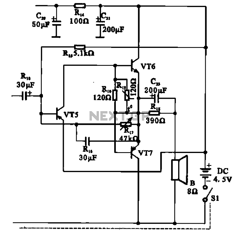
The transistor radio features a common output transformerless (OTL) power amplifier circuit. The VT5 component serves as the bias resistor for the driver stage. VT6 and VT7 form a complementary symmetry configuration, with VT6 being a germanium NPN transistor...
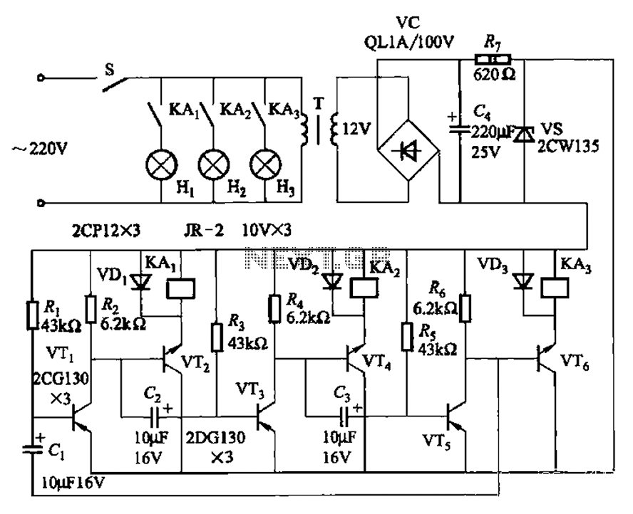
The transistors VTi, VT3, and VTs, along with the RC components, form three distinct multi-resonator oscillators. The oscillation frequency levels are dependent on the values of Ri, R3, Rs, and Cl, as well as Cz and C3s. The circuit comprises...
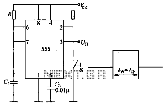
Introduction to the circuit schematic depicted in Figure 3-3. In this configuration, the 555 timer is utilized in a monostable mode, typically activated by a normally open push button switch. The circuit operates in an S-shaped state, where the...
The amplifier's gain is nominally 20 dB. Its frequency response is primarily influenced by the values of a few components, mainly C1 and R1. The schematic diagram's component values yield a frequency response of ±3.0 dB from approximately 120...
This house FM transmitter for your stereo or any other amplifier provides good signal strength up to a distance of 500 meters with a power output of approximately 200 mW. It operates on a 9V battery. The audio-frequency modulation...
The time is set by potentiometer R2, which provides a range from 1 second to 100 seconds, using a timing capacitor C1 of 100 µF. The output at pin 3 is normally low, keeping the relay in the off...
Warning: include(partials/cookie-banner.php): Failed to open stream: Permission denied in /var/www/html/nextgr/view-circuit.php on line 713
Warning: include(): Failed opening 'partials/cookie-banner.php' for inclusion (include_path='.:/usr/share/php') in /var/www/html/nextgr/view-circuit.php on line 713