
CR-5000 PCB Board Designer

The CR-5000 EDA design suite is a sophisticated toolset for electronic design automation, specifically focused on printed circuit board (PCB) design. It employs a constraints-driven methodology that integrates the entire design process, starting from schematic capture and extending through to board layout and the generation of manufacturing data. This approach ensures that design rules and constraints defined at the outset are consistently applied throughout the entire workflow, which significantly enhances the reliability and manufacturability of the final product.
The suite facilitates a streamlined design process where engineers can utilize a common component database, ensuring that all components used in the design are standardized and easily accessible. This commonality not only helps in maintaining design integrity but also accelerates the design cycle, allowing for quicker iterations and modifications.
The schematic capture feature allows designers to create detailed circuit diagrams that accurately represent the electrical connections between components. This is followed by the board layout stage, where the physical arrangement of components on the PCB is optimized for both performance and manufacturability. The constraints-driven nature of the design suite means that any changes made during the layout phase will automatically update the schematic and vice versa, reducing the potential for errors.
Finally, the output of manufacturing data is a critical aspect of the CR-5000 suite, as it generates the necessary files required for PCB fabrication and assembly. This includes Gerber files, Bill of Materials (BOM), and assembly drawings, which are essential for ensuring that the manufactured product meets the original design specifications.
Overall, the CR-5000 EDA design suite is designed to enhance efficiency, reduce time-to-market, and ensure high-quality electronic products by employing a comprehensive and integrated approach to PCB design.The CR-5000 EDA design suite provides the most advanced PCB design functionality currently available. It is constraints driven, from schematic capture through board layout, to the output of manufacturing data.
This means that the rules you apply early in the design process are maintained right through to manufacturing. So products are right first time, manufacturable first time, and get to market fast. A common component database is used throughout the process, 🔗 External reference
Related Circuits
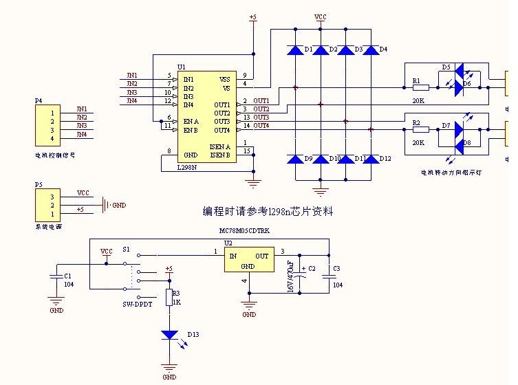
The L298N driver module incorporates the ST L298N chip, commonly utilized to drive two DC motors with voltage ratings between 3V and 30V. It features a 5V output interface that provides power for 5V single-chip circuitry and supports 3.3V...
Here is a link to the ExpressPCB layout for this compressor. If you are not familiar with ExpressPCB, look it up. They provide a layout tool that is very easy to use, and you can have boards manufactured for...

This relay driver enhances the input impedance using a standard BC547 NPN transistor (or its equivalent). It is a widely used driver capable of operating various relays, including reed relays. Transistors Q1 and Q2 function as a simple common-emitter...
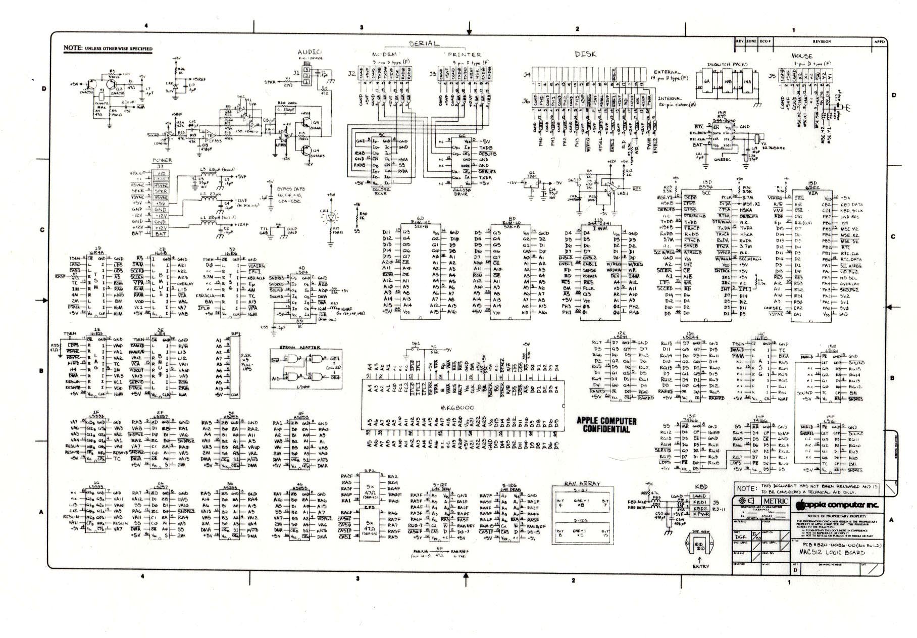
The following is one of the rare and significant documents at DigiBarn, the only known copy of the complete schematic specification for the 512K Macintosh Logic Board. Co-authored by Daniel Kottke, this design served as the foundation for the...
CPU NatSemi Geode operating at frequencies of 200/233/266/300 MHz (with a default speed of 233 MHz on-board) or refer to the Geode link. The VGA/LCD interface is NS GX5530, featuring shared memory of 2.5MB, supporting CRT displays and 18-bit...
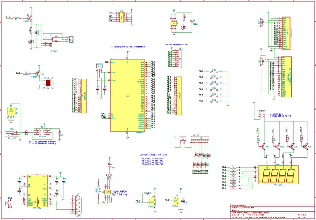
A circuit diagram was created using KiCad, which is considered an excellent free software for designing electronic diagrams and printed circuit boards. KiCad is a powerful open-source software suite that allows engineers and hobbyists to design electronic circuits and...