
Original Macintosh 512K Logic Board Schematic

The 512K Macintosh Logic Board schematic is a pivotal document in computing history, representing a significant advancement in personal computer design during the early 1980s. This schematic encapsulates the architecture of the Macintosh system, showcasing the integration of various components, including the CPU, RAM, ROM, and peripheral interfaces. The design emphasizes modularity and upgradeability, allowing users to expand their systems beyond the initial memory specifications.
The logic board features a Motorola 68000 microprocessor, which was central to the Macintosh's performance capabilities. The schematic details the connections between the CPU and other essential components, such as the memory banks, which are configured to support up to 512K of RAM. The layout illustrates the bus architecture, which facilitates communication between the CPU and memory, as well as the input/output interfaces for peripheral devices.
The design also includes a ROM chip that stores the Macintosh operating system, enabling the system to boot up and run applications. The schematic specifies the pin configurations and electrical characteristics necessary for proper functionality, ensuring that each component operates within its designated parameters.
Furthermore, the foresight of the engineers is evident in the design's emphasis on upgradability. By accommodating additional RAM, the logic board allowed users to enhance their computing experience, reflecting the evolving needs of early Macintosh users. This strategic decision not only improved the longevity of the Macintosh but also contributed to its reputation as a user-friendly and adaptable computing platform.
Overall, the 512K Macintosh Logic Board schematic is not merely a technical document; it represents a milestone in the evolution of personal computing, encapsulating the innovative spirit and design philosophy of its creators.The following is one of the most rare and special documents here at the DigiBarn, the only known copy of the complete schematic specification of the 512K Macintosh Logic Board. Daniel Kottke co-authored this design which served as the basis for the 64K Macintosh prototypes and then the 128K launch Macintosh in January 1984.
This may be the last ma jor computing system completely designed on a single sheet of paper (with all the ins and outs specified for the chips). The original D sized diagram has not been found but Daniel provided us with a smaller facsimile of the same time period.
Legend had it Steve Jobs ordered a 128K logic board to be designed but the engineers, knowing that the first adopters of the Mac would upgrade their memory quickly, designed it to house 512K to allow upgradability. See more pictures of Daniel Kottke`s early Apple Macintosh circuit boards here. 🔗 External reference
Related Circuits
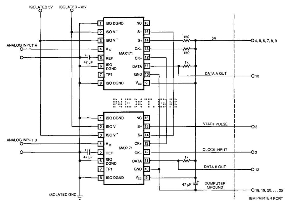
An IBM PC can operate two 12-bit A/D converters via its printer port. The converters' serial outputs utilize only two of the printer port's eight data lines (DATA A OUT, DATA B OUT). The IBM PC's printer port does...
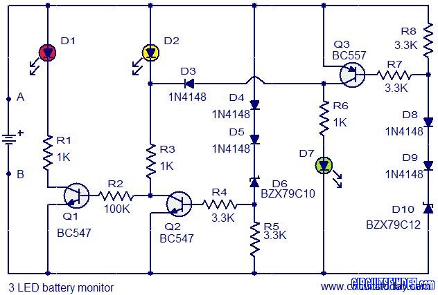
This is the circuit diagram of a 3 LED bar graph type battery monitor circuit that is ideal for monitoring the voltage level of an automobile battery. When battery voltage is 11.5V or less, transistor Q1 will be on...

This mini logic analyzer is a tool that allows users to observe the logic transitions (0 or 1) of digital data signals on an LCD display. Digital data signals can be sourced from various electronic components, such as the...
Two-Tone Siren Circuit Schematic Using One IC. This circuit is designed for children's entertainment and can be installed on bicycles, battery-powered cars, motorcycles, as well as models and various games and toys. It includes a switch (SW1) for operation. The...

The complete hardware schematic of the Night Light Saver V6.0 includes an AC line protected by a 1A fuse (F1). Any short circuit caused by the components of the saver will blow the fuse. Resistor R1 and capacitor C1...
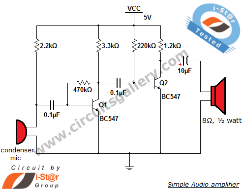
The output of the condenser microphone is coupled through a 0.1 µF coupling capacitor, which serves to eliminate DC components from the audio signal. Transistor Q1 is configured in a collector-to-base biasing mode, achieved with a 470kΩ resistor. This...