
Crossover For Subwoofer
The crossover network is an essential component for integrating a subwoofer into an existing audio system, particularly when leveraging passive filtering techniques. The network's design allows for seamless connectivity to a standard loudspeaker output, facilitating easy installation without the need for external power supplies typically required by active filters.
The first-order low-pass filter configuration ensures that frequencies above the designated cutoff point are attenuated, thereby preventing higher frequency signals from reaching the subwoofer. The adjustable cut-off frequency, controlled by potentiometer P2, allows for flexibility in tuning the system according to the acoustic characteristics of the environment and the specifications of the subwoofer being used. The range of 50 Hz to 160 Hz is particularly effective for various audio applications, ensuring that the subwoofer operates within its optimal range while blending harmoniously with the existing loudspeakers.
The voltage divider formed by resistors R1 and R2, along with P1, is critical for interfacing with amplifiers that provide around 50 watts of output. This ensures that the signal levels are appropriately managed, preventing distortion and potential damage to the subwoofer amplifier. The input capacitance provided by C1, in conjunction with R3 and P2, is tailored to accommodate the typical input resistance of 47 kΩ found in many subwoofer amplifiers. Adjustments to C1 may be necessary if a different input resistance is encountered, ensuring that the filter maintains its effectiveness.
Proper grounding is crucial for the reliability of the audio system. The connection of the loudspeaker signal line ground to the subwoofer amplifier ground mitigates potential ground loop issues, which can introduce noise and affect sound quality. The ability to reverse the phase of the subwoofer by swapping the wires allows for fine-tuning of the system's phase alignment, which can significantly enhance the overall listening experience.
In summary, this passive crossover network is a versatile and efficient solution for integrating a subwoofer into an existing audio setup, providing essential filtering capabilities while maintaining system integrity and sound quality.The crossover network is intended for use when an existing audio installation is to be extended by the addition of a subwoofer. Often, this additional loudspeaker is one that has been lying around for some time. If its frequency response extends down far enough, all is well and good, but a filter is then needed to cut off any frequencies above, sa
y, 150 Hz. Often, a subwoofer network is an active filter, but here this would necessitate an additional power supply. The present network is a passive one, designed so that the speaker signal of the existing system can be used as the input signal.
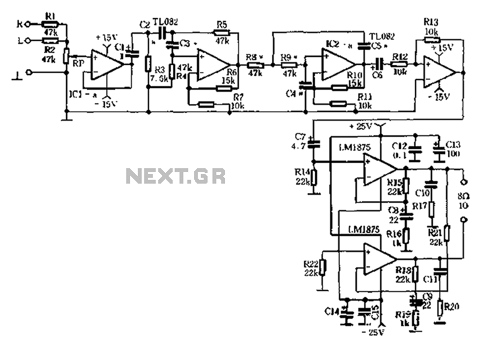
Since the bass information is present in both (stereo) loudspeakers, the signal for the sub woofer can simply be tapped from one of them. The network is a 1st order low-pass filter with variable input (P1) and presettable cut-off frequency (P2).
The signal from the loudspeaker is applied to terminal LSP`. Voltage divider R1-R2-P1 is designed for use with the output signal of an average output amplifier of around d 50 W. The crossover frequency of the network may be varied between 50 Hz and 160 Hz with P2. The values of R3, P2, and C1, are calculated on the assumption that the subwoofer amplifier to be connected to K1 has a standard input resistance of 47 k.
If this figure is lower, the value of C1 will need to be increased slightly. It is advisable to open the volume of the subwoofer amplifier fully and adjust the sound level with P1. This ensures that the input of the subwoofer amplifier cannot be overloaded or damaged. Make sure that the ground of the loudspeaker signal line is linked to the ground of the subwoofer amplifier.
If phase reversal is required, this is best done by reversing the wires to the subwoofer. If notwithstanding the above additional protection is desired at the input of the subwoofer amplifier, this is best effected by overload protection ` elsewhere in this site. 🔗 External reference
Related Circuits
The amplifier can be assembled by a reasonably experienced hobbyist in about three hours. The metalwork will take somewhat longer, and this is especially true for the high continuous power variant. Even so, it is simple to build, compact,...
Audio equipment utilizes the left and right channel signal from the former speaker output terminals. The Rl and RZ mixed units are processed through a buffer (IC1a) before passing through a high and low pass filter. The filter employs...
This is a subwoofer low-pass filter circuit, which is another variant based on the discharge from ST Microelectronics' TL062. The TL062 is a dual high-input impedance J-FET operational amplifier characterized by low power consumption and a high slew rate....
This simple subwoofer circuit is designed to connect to an existing car stereo amplifier, providing the additional "punch" often required for music by driving a subwoofer. Since very low frequencies are omnidirectional, a single amplifier is necessary to drive...
In essence, it uses the same principle as a graphic equaliser, but the simulated inductors are made variable, so the frequency can be swept back and forth. The four 10K pots provide cut (when on the left or anti-clockwise...
This is a true subwoofer circuit designed specifically for 15- to 18-inch woofers and is not compatible with 6- or 8-inch subwoofers. It features a bass-reflex design. The true subwoofer circuit operates by utilizing a bass-reflex enclosure, which enhances low-frequency...
Warning: include(partials/cookie-banner.php): Failed to open stream: Permission denied in /var/www/html/nextgr/view-circuit.php on line 713
Warning: include(): Failed opening 'partials/cookie-banner.php' for inclusion (include_path='.:/usr/share/php') in /var/www/html/nextgr/view-circuit.php on line 713