
Radio circuits built

The receiver design incorporates several key components and configurations that enhance its functionality and adaptability. The LM386 amplifier stage is a low-voltage audio power amplifier capable of delivering sufficient output to drive an 8-ohm speaker, making it suitable for portable applications. The choice of a magnetic loop antenna over a ferrite loopstick antenna significantly increases the receiver's sensitivity and selectivity, especially for AM frequencies. The directional nature of the magnetic loop antenna allows for precise tuning and reception of specific stations, minimizing interference from adjacent frequencies.
The implementation of a switch to toggle between speaker and earphone modes provides versatility in listening options, accommodating different user preferences and situations. The low current draw in earphone mode extends battery life, making the receiver practical for extended use without frequent battery replacements. The use of rechargeable NiMH batteries aligns with sustainable practices, while the option for alternative power sources, such as solar panels, enhances the receiver's usability in outdoor settings.
The modular design, featuring screw connections for easy component swaps, promotes experimentation and upgrades. The addition of a handle for portability and the careful arrangement of controls and components within the chassis facilitate user interaction and ease of use. The adjustments made to capacitor values within the circuit reflect a hands-on approach to optimizing audio performance, ensuring that sound quality meets user expectations.
In summary, this modified receiver exemplifies a thoughtful integration of components and design principles, resulting in a highly functional and adaptable AM radio receiver that caters to a variety of listening environments and preferences. The ongoing enhancements and experimentation with the design further illustrate the potential for innovation within the realm of amateur radio projects.This receiver is a modification of Charles Wenzel`s Two Transistor Reflex Radio. Instead of a ferrite AM loopstick antenna, I use a magnetic loop antenna, and I added an LM386 amplifier stage to drive an 8-ohm speaker. There is a switch to select whether this amplifier should be used to power the speaker or whether crystal earphone listening is d
esired. I use six AA rechargeable NiMH batteries to provide the 8V power supply, but a 9V alkaline battery or a 6V lantern battery work just fine. I think even a small solar cell array would suffice to power this thing if you were camping on a sunny enough day!
Prototype receiver on breadboard. I will soon move all parts currently mounted on the breadboard to a soldered circuit board. I will also add interface connections with screws on the wood base, so that I can swap out other receiver modules to the same wooden box. Update 25 August 2009. The finished AM receiver. The detector and audio amplifier circuitry is now soldered to a permanent circuit board. I added a handle to make it easy to carry the radio around. Close up view of the inside of the finished receiver. I have the schematics folded up inside a small zipper-style plastic bag, attached to the inside of the wood frame using Velcro.
The screw connections facilitate removing the circuit board and replacing it with other experimental designs. The magnetic loop antenna is depicted as a transformer. It is actually a pair of hand-wound rectangular loops of enameled magnet wire, about 5. 5 inches by 4. 5 inches. If I build another one of these receivers, I will wrap maybe 16 or 18 turns instead of 20 on the tuner side to bring down the inductance so that I can tune higher on the AM band.
The antenna is highly directional. You have to rotate the radio to aim it at the desired radio station. More specifically, for strongest reception of a nearby station (i. e. not receiving by skywave propagation) the radio station must lie in the plane of the loop, and that plane must be at right angles to the ground. (Apparently the magnetic component is polarized horizontally. ) If you rotate the radio 180 ° around a vertical axis, its reception of a given station will be the same.
This directionality can be used to advantage. Where I live there are two radio stations close together in frequency: 1030kHz and 1060kHz. However, it is fortunate for me that they are about 60 degrees apart in terms of compass direction from my house. Selectivity of this receiver is pretty good, and with proper aiming I can almost completely block out one of the two stations and focus on the other.
I even put felt feet on the bottom of the chassis (the kind used on chair legs to prevent scuffing the floor), so that I can easily spin the radio around without scratching the table it is on! UPDATE (27 August 2009): Try out my online Azimuth/Distance calculator page to determine the exact compass direction and distance of a radio station!
Use Google Maps or Google Earth to find your exact latitude and longitude. Use this as "Point A" in the calculator. Use the FCC online AM radio station database to find the coordinates of the transmitter. Use this as "Point B". The calculated azimuth tells you how many degrees clockwise from North the station is from your location. The Band switch selects whether you are tuning the lower or higher end of the AM broadcast band. When the 220pF capacitor C1 is connected in parallel with the tuning capacitor, the tuner can reach down to well below 540kHz.
With C1 disconnected, the tuner can reach as high as 1100 kHz. Where I live there aren`t any stations I care about above this frequency, but in the future the aforementioned decrease in the number of turns in the magnetic loop antenna should better fit the AM band. The Output Select switch (see lower left in schematic) toggles between driving the high-impedance crystal earphone or the 8-ohm speaker via the LM386 amplifier.
In earphone mode, the receiver draws a miserly 1. 5mA of battery current; that could make your battery last for hundreds of hours! (At least, I think so. I am still in the process of testing practical battery life with my NiMH rechargeable batteries. ) In speaker mode, the current consumption is more like 8mA to 15mA, depending on the volume setting. When the Output Select is set for earphone mode, the Volume knob has no effect. Use the Regen to get the best volume you can without distortion. You won`t get head-banging rock concert volume, but you will be able to hear talk radio quite clearly.
If the 470K resistor R7 is replaced with a wire, you get problems with oscillations (so-called "motor-boating"). Looking at the LM386 data sheet, I see that there is a 50K resistance between the amplifier`s positive and negative inputs.
Apparently R7 limits the audio-frequency current flowing through C7 enough to stabilize the circuit. When I started this project, I had a wire instead of R7 and I was trying to figure out how to fix the oscillation problem. I disconnected the wire and noticed that if I touched one of my fingers to the wiper pin of the Volume potentiometer, and another finger to pin 3 of the LM386, the radio suddenly started working!
I played around with various resistors in the range 100K to 1M and settled on 470K as a good value. If you build this receiver, try various values; another might work better for you. The potentiometer I use for the Volume knob has a built-in SPDT switch. I use this as my power switch: when Volume is turned all the way down, it clicks off. My design is a lot bulkier than is really needed, but I did this on purpose to make future experimentation easier. I want a lot of room for my large hands to move around! I want to be able to re-use the chassis, antenna, and controls for other experimental circuits, so I`m designing it to allow the receiver circuit board to be swapped out with other designs.
The LM386 data sheet gives an example value of 10 µF for the capacitor I call C10 in the schematic. I started out with this value, but I found the audio to sound "muddy" when the volume knob was turned up too high. In fact, there was a tendency to oscillate past a certain point. After experimenting, I settled on 2. 2 µF as a better fit. It reduces bass while leaving midrange and treble strong, and allows better fidelity sound at higher volume settings.
I tried as low as 0. 2 µF, but at that point the sound was too tinny and wasn`t capable of the volume level I wanted. Tonight (28 August 2009) I had fun with an experiment to figure out the inductance of the tuning coil (the 20 turns of magnet wire), along with its so-called "parasitic" capacitance. I tuned the receiver to 6 different radio stations. For each radio station, I turned the receiver off, disconnected one of the tuning capacitor wires, and measured th on coil geometry.
🔗 External reference
Related Circuits

This game can be played individually or with friends. The circuit consists of a timer IC, two decade counters, and a display driver paired with a 7-segment display. The objective of the game is straightforward: the player who reaches...
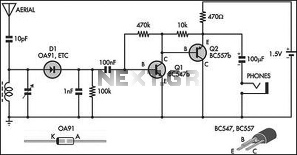
This circuit is an amplified crystal set. The inductor can be a standard AM radio ferrite rod antenna, while the tuning capacitor is a variable plastic dielectric gang designed for small AM radios. The aerial tuned circuit feeds diode...
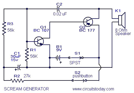
Multi Tone Alarm Description This is a simple and easy-to-build multi-tone alarm circuit that can be used in burglar alarms or sirens. The circuit is based on the dual op-amp MC1458 and LM380. The two op-amps inside the MC1458...
This schematic illustrates a high-quality AM radio receiver circuit centered around the MK484 AM radio integrated circuit (IC). The MK484 is known for its high sensitivity and superior performance, featuring only three leads and housed in a TO-92 package....
Build-in charger for instruments powered by single lithium-ion or Li-Pol accumulator. If external power supply not connected to charger, current back from the accu charger is very small. New version improved temperature stability and Not Needed NTC thermistor. After...
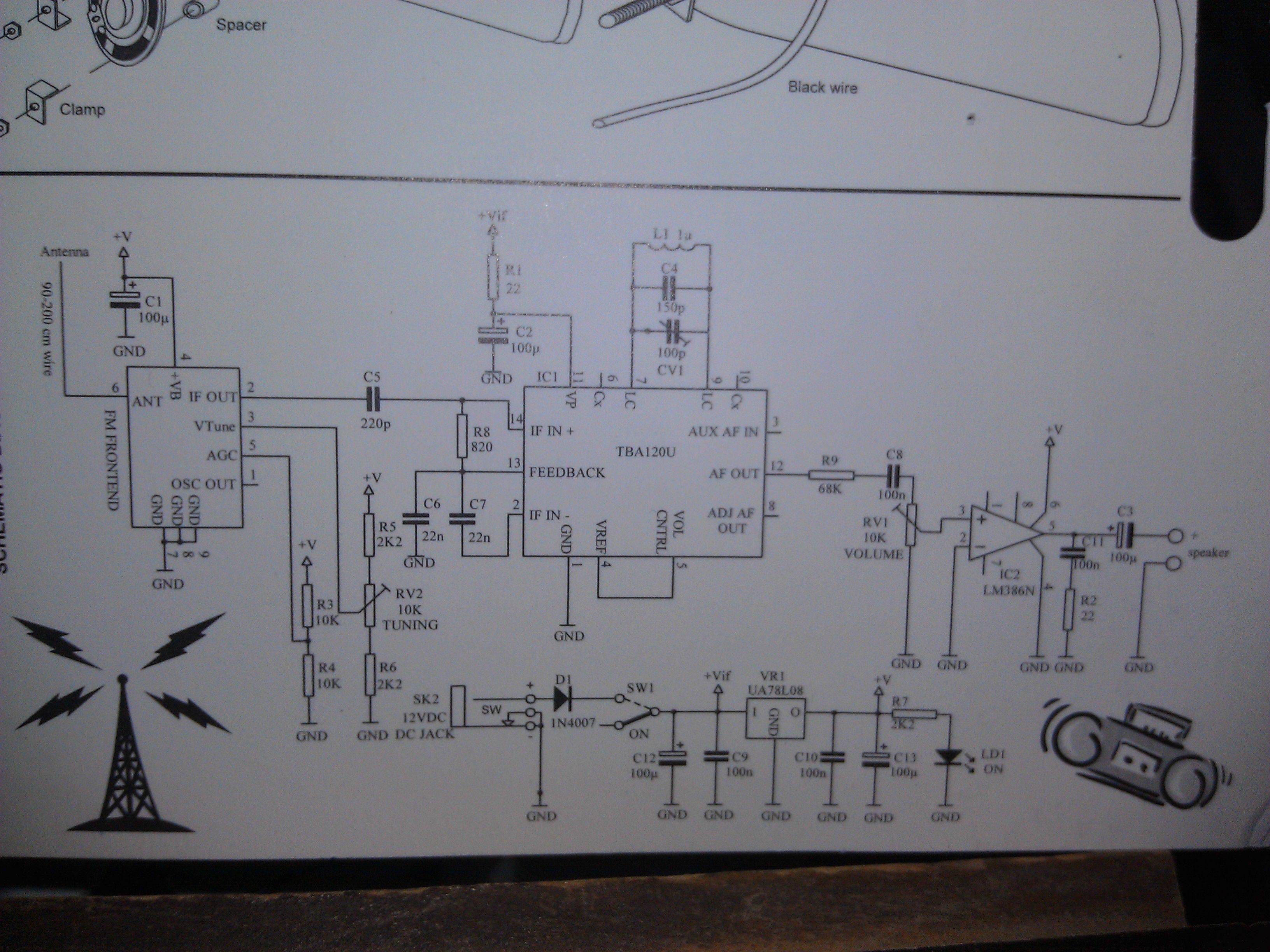
An FM Radio kit manufactured by Velleman-Kit and sold by Radioshack was recently assembled. The assembly process took approximately two hours, primarily due to distractions. The instructions provided are generally easy to follow, but they lack explicit details regarding...