
simple dimmer circuit
The described circuit employs a triac as a key component for controlling the power supplied to a load, such as a tungsten or LED lamp. The operation begins with the potentiometer, which adjusts the resistance in the circuit. This adjustment influences the charge time of capacitor C4, which is critical for the timing of the firing pulse. The resistors R3, R4, and R5, along with the potentiometer P1, form a voltage divider network that determines the charging rate of C4.
Once the voltage across C4 reaches a threshold level, the diac D transitions from a non-conductive to a conductive state. This transition generates a pulse that triggers the gate of the triac. The triac, once triggered, enters a conductive state and allows current to flow to the load, effectively controlling the power delivered to the lamp. The design enables smooth dimming of the light output by varying the phase angle of the AC waveform delivered to the lamp.
The circuit's performance can be affected by the values of the resistors and the capacitor, which need to be carefully selected to achieve the desired dimming range and response time. Additionally, the characteristics of the lamp (tungsten or LED) will influence the overall behavior of the circuit, particularly regarding the minimum load required for stable operation. Proper thermal management and component ratings are essential to ensure reliability and prevent overheating during extended use.A potentiometer is controlling the firing point of the triac. Capacitor C4 is charged via resistors R3, R4, P1, and R5. After a certain time, dependant on the potentiometer, the charge contained in C4 is large enough for the dimmers diac D to start conducting, so that a firing pulse is applied to the gate of the triac. Consequently the triac conducts and power is transferred from the dimmer to the tungsten or LED lamp.
. 🔗 External reference
Related Circuits
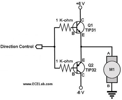
The following circuit illustrates a two-transistor DC motor driver circuit diagram. This circuit utilizes the TIP32 transistor. Features: operates in... The two-transistor DC motor driver circuit is designed to control the operation of a DC motor using two NPN transistors,...
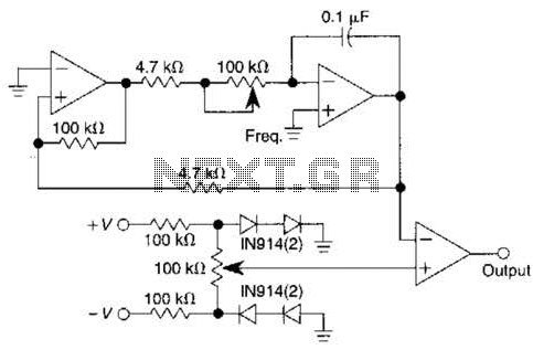
This pulse generator utilizes a single integrated circuit (IC) and six passive components to achieve a frequency range of 400 to 4000 Hz, with an adjustable duty cycle ranging from 1% to 99%. The circuit employs a threshold detector...
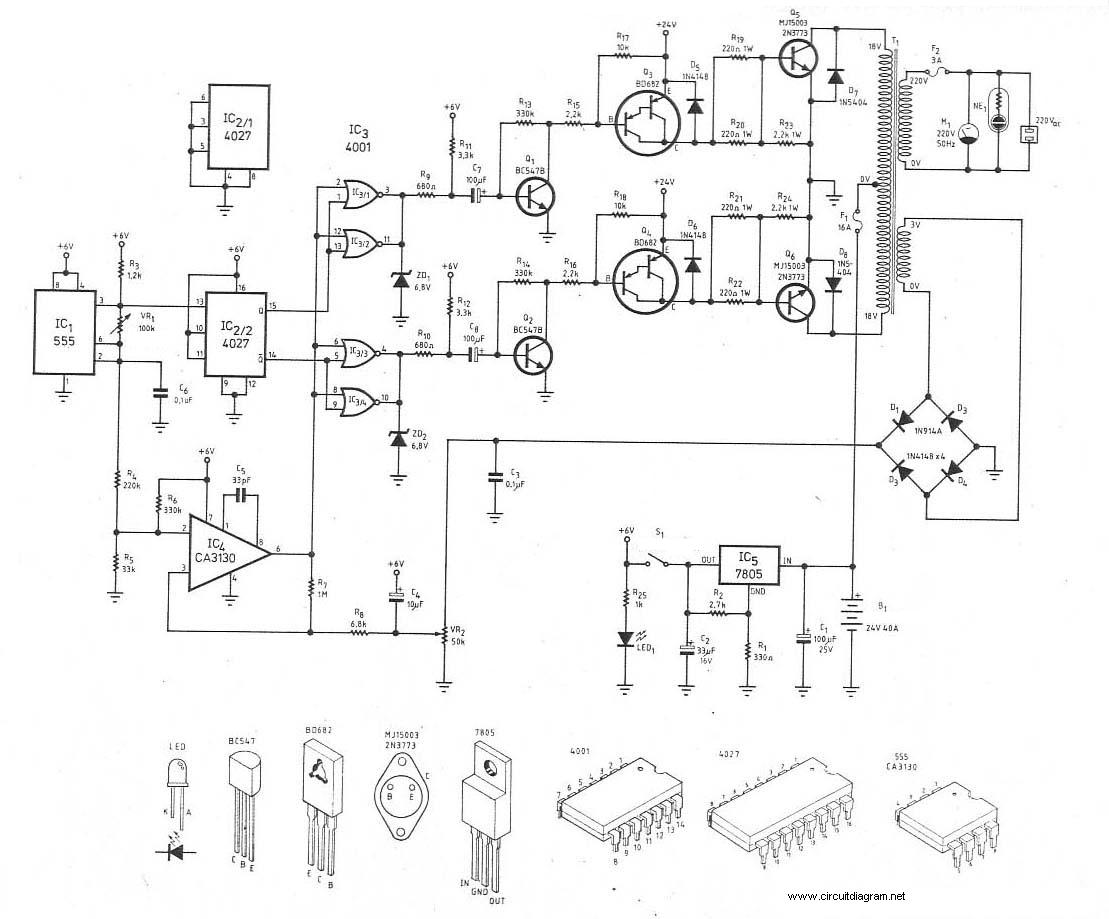
This is the schematic diagram of a 300W power inverter circuit. The inverter utilizes the MJ15003 power transistor for final amplification. If the MJ15003 transistor is difficult to source, it can be replaced with a 2N3773. The inverter is...
This circuit is a wireless car alarm system constructed using two modules: a transmitter module and a receiver module. It operates on FM radio waves and is suitable for vehicles with a power supply of 6-12VDC. A voltage stabilizer...
Almost all 24V power systems in trucks, 4WDs, RVs, boats, etc., utilize two series-connected 12V lead-acid batteries. The charging system can only sustain the total voltage of the individual batteries. If one battery is failing, this circuit will illuminate...
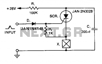
Capacitor C1 is charged to +28 V through resistor R1 and stores energy for firing the squib. A positive pulse of 1 mA applied to the gate of SCR1 will cause it to conduct, discharging C1 into the squib...