
Audio-rf signal tracer probe
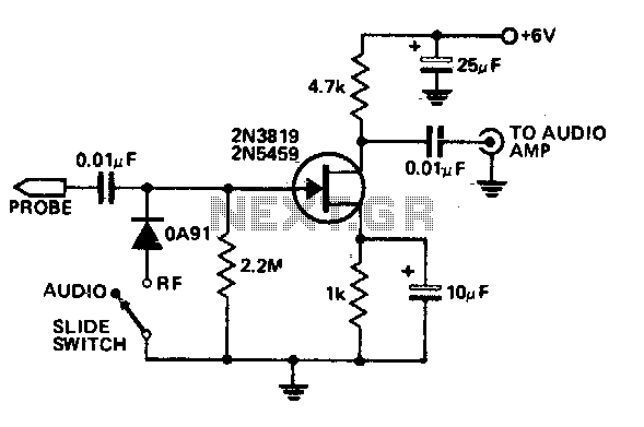
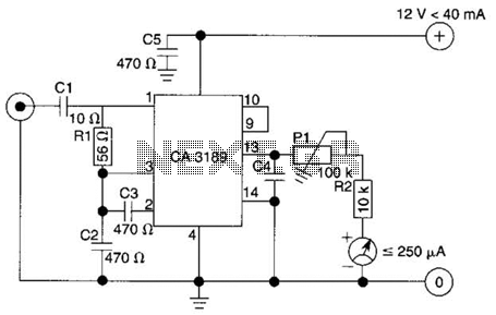
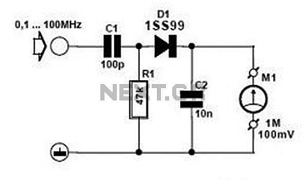
The signal tracer is designed to facilitate the diagnosis and alignment of radio frequency (RF) circuits, particularly in receivers and low-power transmitters. The device operates by switching to RF mode, allowing it to detect modulation on incoming signals through a diode. The diode acts as a rectifier, converting the RF signal into a form that can be amplified. The subsequent amplification is performed by a Field Effect Transistor (FET), which enhances the signal strength for easier analysis.
The use of a twin-core shielded lead is critical in this setup. It serves a dual purpose: it connects the probe to an external amplifier, ensuring that the signal can be processed further, and it provides a power supply of 6 volts to the circuit. This power supply is essential for the operation of the FET and the overall functionality of the signal tracer.
The circuit design should include appropriate biasing for the FET to ensure optimal performance. Additionally, the diode should be selected based on its frequency response to ensure it can effectively detect the modulation present in the RF signals being tested. The shielding of the lead is also important to prevent interference from external electromagnetic fields, which could distort the signals being traced.
Overall, this economical signal tracer represents a valuable tool for technicians and engineers working in the field of electronics, enabling efficient troubleshooting and alignment of RF systems. Proper implementation of the circuit components and connections will enhance the reliability and accuracy of the device in various applications.This economical signal tracer is useful for servicing and alignment work in receivers and low power transmitters. When switched to RF, the modulation on any signal is detected by the diode and amplified by the FET A twin-core shielded lead can be used to connect the probe to an amplifier and to feed 6 volts to it. 🔗 External reference
Related Circuits
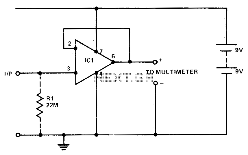
A 741 operational amplifier (op amp) is utilized with complete AC and DC feedback to achieve a typical input impedance of 10^11 ohms and unity gain. To minimize hum and radio frequency (RF) interference, it is recommended that the...
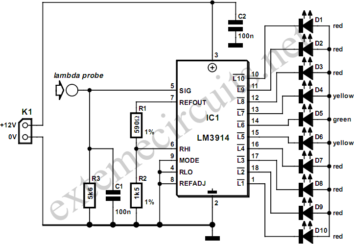
A lambda probe, also known as an oxygen sensor, is commonly found on the exhaust systems of vehicles that operate on unleaded fuel. Once it reaches its normal operating temperature of approximately 600 degrees Celsius, the lambda probe generates...
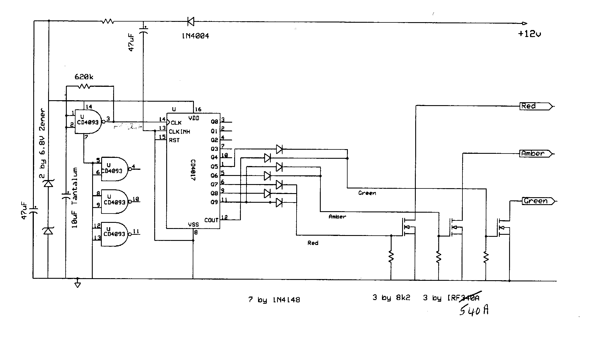
A board is to be designed with a single input of 120 volts and 600 watts, which will provide more than three outputs, each rated at 120 volts and 200 watts. These outputs will be designated as A, B,...
This logic probe utilizes a single CMOS integrated circuit (IC) to indicate three logic states: High, Low, and Pulsing. If the probe input is in a high impedance state, which occurs when it is not connected to a circuit,...
The design of the digital logic probe centers around a pair of complementary bipolar transistors, which, in this application, are used as electronic switches. The digital logic probe is a diagnostic tool utilized for testing and analyzing digital circuits. The...
Comprehensive information about RF Probe Circuits is available. Users can learn about and download RF Probe Circuit designs online. RF Probe Circuits are essential tools for testing and analyzing radio frequency signals in various applications, including telecommunications, broadcasting, and electronic...
Warning: include(partials/cookie-banner.php): Failed to open stream: Permission denied in /var/www/html/nextgr/view-circuit.php on line 713
Warning: include(): Failed opening 'partials/cookie-banner.php' for inclusion (include_path='.:/usr/share/php') in /var/www/html/nextgr/view-circuit.php on line 713