
LM359 Voltage Controlled Oscillator Circuit

The voltage-controlled oscillator (VCO) is a critical component in various electronic applications, including phase-locked loops (PLLs), frequency modulation, and signal generation. The core functionality of the VCO is to produce an output frequency that varies in response to an input control voltage. This allows for precise frequency modulation based on external signals or control inputs.
In the described circuit, the operational characteristics hinge on the configuration of the amplifier and the selection of resistors R1 and R2. The relationship between these resistors is crucial; specifically, R2 must be set to twice the value of R1 to ensure that the VCO operates within its intended frequency range. The amplifier input voltage 'd' is critical, as it sets the baseline for the oscillation frequency, while the hysteresis value 'h' of the DM1474 helps stabilize the output and reduce noise.
The ability of the VCO to achieve operational frequencies of up to 5MHz indicates its suitability for high-speed applications. The design must consider factors such as power supply stability, temperature variations, and component tolerances to maintain performance across its operational range. Additionally, proper layout and decoupling techniques should be employed to minimize interference and ensure reliable operation in a variety of environments.Voltage controlled oscillator (VCO) is similar to a voltage to frequency converter (VFC), an oscillator which its output frequency is determined by a control voltage input. This is the figure of the circuit; Where d is the amplifier input voltage = 0. 6V, h=hysteresis of DM1474 (typically = 1V). R2 must beequal to 2R1 for proper operation. Using th is circuit, operation up to 5MHz can be achieved. 🔗 External reference
Related Circuits
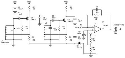
One type of metal detector is a beat frequency oscillator (BFO). The operation of metal detectors relies on changing the characteristics of the oscillator when it is near a metal object detected by the sensor. The detector functions based...
This is a basic 555 squarewave oscillator used to produce a 1 kHz tone from an 8-ohm speaker. In the circuit on the left, the speaker is isolated from the oscillator by the NPN medium power transistor, which also...
This document explains how to connect lights so that they flash when the phone rings. This setup is particularly beneficial in noisy environments, such as workshops, where it is challenging to hear the phone ringing. The ring detection component...
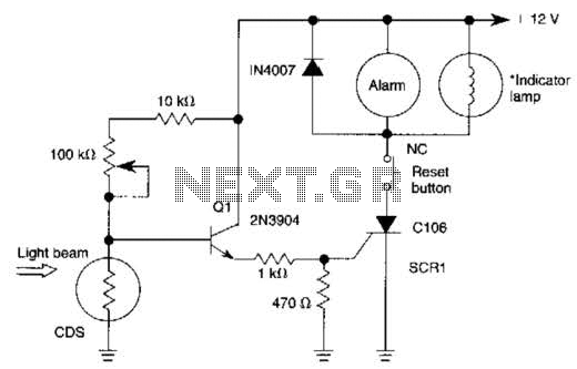
When the light beam that falls on the CDS photocell is interrupted, the transistor (EN3904) conducts, triggering SCR1 (CI06) and activating the alarm bell. SI resets the SCR. The alarm bell should be a self-interrupting electromechanical type. The lamp...
This regulator is suitable for devices that need up to 1mA. For higher output current, the resistors would have to be scaled down in reverse proportion to the peak current expected. With the resistor values shown, the regulator draws...
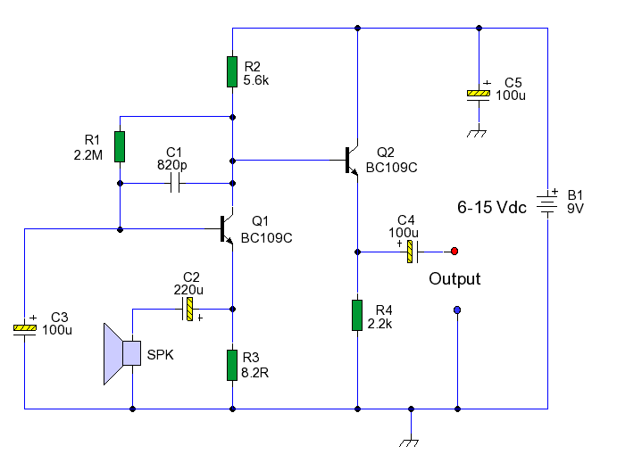
This circuit enables the use of an inexpensive loudspeaker as a microphone. Sound waves that reach the speaker cone create fluctuations in the voice coil. The movement of the voice coil within the speaker's magnetic field generates a small...
Warning: include(partials/cookie-banner.php): Failed to open stream: Permission denied in /var/www/html/nextgr/view-circuit.php on line 713
Warning: include(): Failed opening 'partials/cookie-banner.php' for inclusion (include_path='.:/usr/share/php') in /var/www/html/nextgr/view-circuit.php on line 713