
Jfet Amp With Current Source Biasing Circuit

The circuit incorporates an MPF102 JFET configured as a current source, which is connected to the source terminal of a 2N3906 bipolar junction transistor (BJT). The MPF102 operates in the saturation region, providing a stable and accurate current output. The characteristics of the MPF102 ensure that variations in the supply voltage or temperature have minimal impact on the current flowing through the 2N3906.
The 2N3906 transistor serves as a common-emitter amplifier, where the drain current is modulated by the base current. By utilizing the MPF102 as a current source, the design enhances the linearity and stability of the amplification process. The configuration allows for a well-defined operating point, improving the overall performance of the circuit.
To implement this configuration, the gate of the MPF102 is typically connected to a biasing network that sets the desired current level. The source lead of the 2N3906 is connected to the drain of the MPF102, ensuring that the current provided by the JFET is used effectively by the BJT. Additional passive components, such as resistors and capacitors, may be included in the circuit to filter noise and stabilize the operating conditions.
Overall, this arrangement of an MPF102 current source with a 2N3906 transistor provides a robust solution for applications requiring precise control of drain current, making it suitable for various analog signal processing tasks. A current source (MPF102) in the source lead of bipolar transistor 2N3906 permits accurate control of drain current. 🔗 External reference
Related Circuits
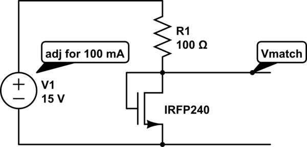
The unit is designed to drive an 80V/10A motor. The current matching circuit is utilized, but there is uncertainty regarding the appropriateness of the MOSFET selection for this application. The circuit for driving an 80V/10A motor typically requires careful consideration...

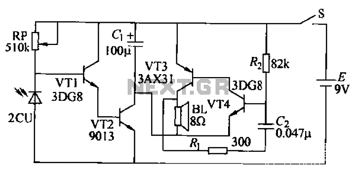
This design aims to restore the classic style of telephones that utilized a pair of gongs to signal an incoming call, evoking a sense of nostalgia with the familiar sound of ringing bells. Presented here is a "Telephone Ring...

The alarm circuit operates as follows: When the power switch SW1 is turned on, the alarm system becomes active. If a magnet is brought close to the spring, the magnetic field attracts the spring, causing the dynamic and static...
Boiling water or cooking with a gas stove can sometimes lead to the fire being extinguished due to water spills, which can result in a significant gas overflow and pose a risk of poisoning. This example describes a stall...
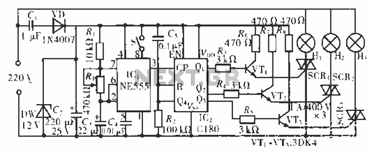
The circuit operates at 220 V AC using a C1 buck converter and a DW regulator. The VD ensures the entire stream is processed, and C2 provides a filtered output of 12 V DC for the voltage supply control...

This add-on circuit can be attached to the solar charger to indicate whether the battery is charging. It lights a red LED to signal that the battery is charging. The described add-on circuit serves as a visual indicator for the...
Warning: include(partials/cookie-banner.php): Failed to open stream: Permission denied in /var/www/html/nextgr/view-circuit.php on line 713
Warning: include(): Failed opening 'partials/cookie-banner.php' for inclusion (include_path='.:/usr/share/php') in /var/www/html/nextgr/view-circuit.php on line 713