
Crystal Filter
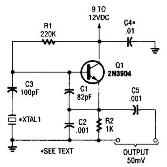
The described circuit utilizes six identical crystals operating at a frequency of 4.433 MHz, which is a common frequency for SSB (Single Sideband) modulation applications. The choice of using crystals from the same manufacturer and with the same serial number ensures that their frequency characteristics are closely matched, minimizing phase discrepancies that could lead to performance degradation in the filter's response.
The filter is designed to have a 6 dB bandwidth of approximately 2.2 kHz, which is suitable for SSB applications where bandwidth efficiency is crucial. The bandwidth can be adjusted by changing the values of the terminating resistors and the trimming capacitor. In this case, a 1 kΩ resistor is used in parallel with an 18 pF capacitor at both the input and output. This configuration allows for fine-tuning of the filter's response, ensuring that the passband ripple is minimized to 2 dB, which is an acceptable level for high-fidelity audio applications.
The circuit layout should ensure that the crystals are arranged in a manner that optimizes their coupling and minimizes parasitic capacitances and inductances. The use of a PCB (Printed Circuit Board) can help achieve this by providing a controlled environment for the components and reducing the impact of external interference.
In summary, the implementation of this SSB filter circuit leverages the economic advantages of low-cost crystals while maintaining performance through careful component selection and arrangement. The resulting filter is capable of providing high-quality signal processing suitable for various communication applications.n the view of the dramatic drop in the price of crystals used in color TV sets, they now represent an economical way of building an SSB filter. The circuit shown in the diagram is for a filter with a 6 DB band width of roughly 2.2 KHz. By terminating the input and output with a 1 K Ohms resistor in parallel with an 18 pf trimming capacitor, passband ripple can be tuned down to 2 DB.
All crystals used in the circuit are 4.433 MHz. Collect all the six crystals from same manufacture with same serial number. 🔗 External reference
Related Circuits
The figure illustrates the FM modulation circuit of a crystal oscillator. FM modulation can be achieved through direct and indirect methods. The direct FM method involves directly altering the frequency of the oscillating circuit. While this approach is straightforward,...
Circuit of a crystal-controlled FM transmitter. The circuit utilizes a crystal oscillator and several power amplifier stages to enhance output power. The crystal-controlled FM transmitter circuit is designed to generate frequency-modulated signals with high stability and precision. At the core...
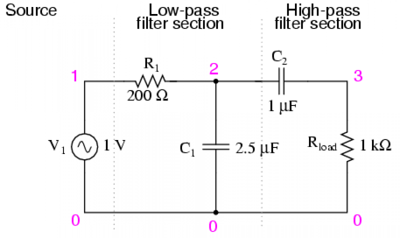
There are applications where a particular band, or spread, or frequencies need to be filtered from a wider range of mixed signals. Filter circuits can be designed to accomplish this task by combining the properties of low-pass and high-pass...
This is a simple Colpitts crystal oscillator for 1 to 20 MHz, which can be easily constructed from spare parts, provided that a crystal is available. The Colpitts oscillator is a type of electronic oscillator that utilizes a combination of...
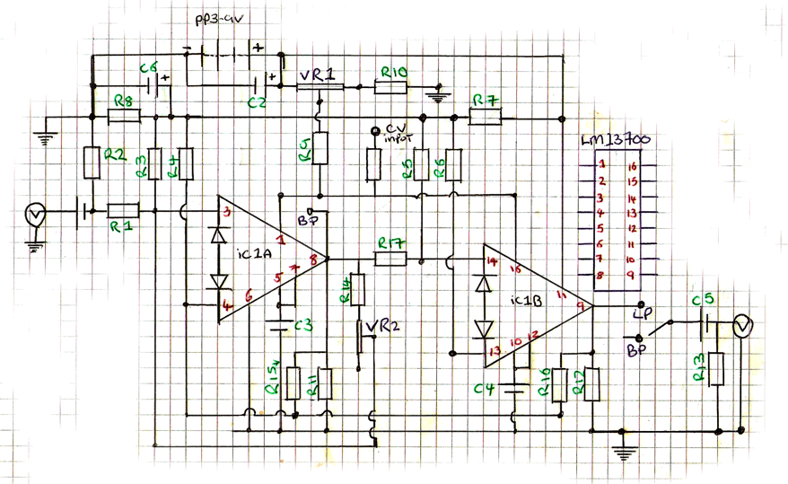
This is a 9V DC powered LM13700 dual transconductance operational amplifier-based filter, highly suitable for battery-powered circuits. The design is adapted from an article by R. A. Penfold for Maplin magazine, incorporating manual filter cut-off and resonance control. At...
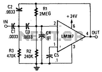
This circuit is a two-section active high-pass filter using an LM387, with a cutoff frequency below 50 Hz at a slope of 12 dB per octave. It will help reduce rumble caused by turntable defects in record systems. The two-section...