
Crystal Locked FM Bug

The described FM transmitter circuit employs a voltage-dependent oscillator stage that leverages the behavior of passive components to modulate frequency based on supply voltage. The circuit design focuses on achieving a balance between range and stability, utilizing coil and capacitor adjustments to achieve the desired transmission frequency within the FM band.
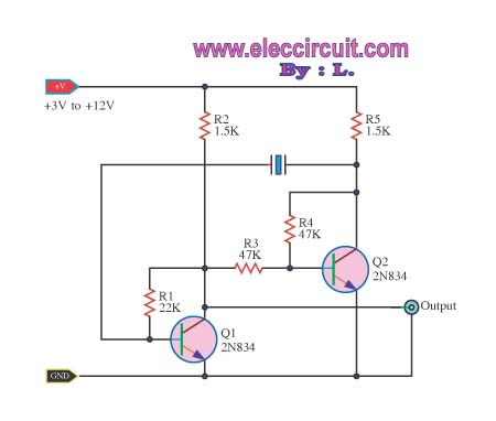
The oscillator circuit typically consists of a transistor configured in a common emitter arrangement, where the emitter circuit incorporates the crystal. This configuration allows the crystal to stabilize the frequency while permitting audio signals to modulate the output. The circuit's input stage is designed to accept audio signals, which are then injected into the base of the transistor. The modulation of the carrier frequency occurs as the audio signal influences the oscillator's operation.
To achieve the desired frequency range, the circuit employs a tripler stage that multiplies the output frequency generated by the oscillator. This stage is critical for converting the stabilized frequency produced by the crystal oscillator into a higher frequency suitable for FM transmission. The tripler stage typically consists of additional active components and passive filters designed to enhance signal integrity and minimize distortion.
In summary, the design of the FM transmitter emphasizes the importance of component selection, circuit configuration, and stability. The use of a crystal in overtone mode, combined with a well-designed tripler stage, enables the circuit to achieve high-quality audio transmission over varying distances while maintaining frequency stability. This approach addresses the inherent challenges of crystal oscillators and provides a reliable solution for FM transmission applications.A number of simple FM devices, (without the use of a crystal) and showed how the power and frequency depends on a number of factors including the voltage of the supply and the design of the stages. The broad term given to the oscillator stage of these transmitters is "voltage dependent" as the frequency of the output is dependent on the voltage of the supply
. We designed transmitters capable of transmitting 100 metres (the Ant), 400 metres (the Amoeba), 800 metres (the Voyager), 1km (the Ultima) and others with ranges between 100 metres and 1km. It was simply a matter of adjusting the spacing of the coil or the value of the capacitor in the oscillator circuit to shift the frequency anywhere on the band.
As the battery voltage fell at the end of its life, the frequency did move slightly. Although this shift was very small, the change was noticeable in some applications, such as long-term monitoring of alarms etc. The only way to achieve this is to have an extremely stable oscillator - one that is independent of the supply voltage.
Designing such a circuit is not an easy task and it has taken us quite a number of attempts to get it to work properly. At last we have come up with a suitable design and we have called it the Crystal Locked Bug - or Xtal Bug for short.
During our designing we had two major problems to overcome. One was getting a low-cost crystal that would produce a frequency on the 88 -108 band and the other was getting good quality audio. When audio is fed into a crystal locked oscillator, it must "pull and push" the frequency of the oscillator - after all, that is why it is called Frequency Modulation.
In other words it must pull and push the oscillator against the rigidity of the crystal and in doing so, the audio gets distorted. This is one of the major problems with a crystal oscillator and to solve this we have placed the crystal in the emitter circuit.
In this position it allows the audio to be injected into the base of the oscillator stage so that it can be combined with the 90MHz carrier (the carrier is the frequency being produced by the stage) without being distorted. Another problem was designing a crystal circuit at 88 - 108MHz. Crystals are not capable of operating directly at this frequency. Most (cheap ones) operate at about 8MHz to 10MHz. This is called their fundamental frequency, if we want a transmitter to operate in the 88 -108 MHz band, we need to use the crystal in its overtone mode.
In this mode a crystal with a fundamental frequency of say 10MHz can he placed in a circuit that is designed to oscillate at a higher frequency - say 30MHz. In other words the circuit components around the crystal want to operate at 30MHz, the crystal merely keeps them operating at EXACTLY this frequency.
In theory you could gel a 10MHz crystal to operate in a circuit at 90MHz but the crystal would only be controlling the circuit every ninth cycle and this is not providing a very tight control. It is much better to use the crystal in one of its lower overtone modes, where the control is much stronger.
As the order of overtone increases, the crystal has less "grip" on controlling the frequency. The most common overtone modes are third (e. g. a 10MHz crystal operating in a 30MHz circuit) and fifth (a 10MHz crystal operating in a 50MHz circuit). We have decided to use the crystal in its third overtone mode and provide a further stage, called a tripler, to get the final required frequency of 90MHz.
The only problem with identifying the frequency of a crystal is some crystals are marked with their third overtone value while others are identified with their fundamental frequency, For instance. 27MHz crystals for CB`s, remote control cars and walkie talkies are generally 3rd overtone crystals and have a fundamental of about 9MHz while computer crystals are generally identified by their fundamental frequency.
Crystal circuits take adv 🔗 External reference
Related Circuits

Using a 12-V supply, this crystal calibrator should prove to be a useful accessory for a shortwave (SW) receiver. Q1 and Q2 form a oscillator, and Q3 is a buffer amplifier. The described crystal calibrator operates on a 12-V power...
The 27MHz quartz crystal oscillator circuit is illustrated in figure 1. The biasing circuit consists of resistors R1, R2, and R3, while C6 serves as the bypass capacitor. The partial voltage circuit includes capacitors C1, C2, C3, and C4...

Since the last update, significant efforts have been directed towards debugging the board. Multiple issues have been identified in the implementation of the DC-DC converter circuitry. However, sufficient evidence has been collected regarding the bug, indicating that it is...
The original BFO, a compact EICO 330 solid-state signal generator, effectively received a variety of distant longwave (LW) beacons. In late 2004 to early 2005, a new One-Active Device (1-AD) contest was introduced to complement the Crystal Set DX...
An oscillator circuit of this nature is often utilized as a clock circuit. This circuit employs a crystal frequency control with a stability of one million hertz. An oscillator circuit designed for clock applications typically generates a periodic signal, which...
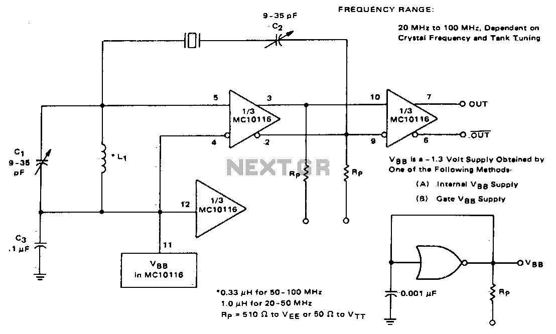
This circuit utilizes an adjustable resonant tank circuit that ensures operation at the desired crystal overtone. Capacitor C1 and inductor L1 form the resonant tank circuit, which can be adjusted to achieve a resonant frequency ranging from approximately 50...