
Mono to Stereo Audio Signal Circuit Converter
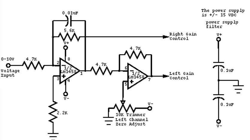
The circuit operates by taking a single mono audio input and splitting it into two outputs, corresponding to the left and right audio channels. The panning effect is achieved through the manipulation of the audio signal levels based on the control voltage input, which ranges from 0 to 10 volts.
When the control voltage is at 0V, the entire audio signal is directed to the left channel, resulting in a fully left-panned output. As the control voltage increases towards 5V, the audio signal is evenly distributed between the left and right channels, creating a centered sound. When the control voltage reaches 10V, the audio signal is fully directed to the right channel.
The circuit may utilize operational amplifiers (op-amps) to ensure that the audio signals maintain high fidelity and low distortion throughout the panning process. The design may include resistors and capacitors that set the gain and frequency response of the audio signals, ensuring compatibility with various synthesizer outputs.
Additionally, the control voltage can be generated by various sources, such as a voltage-controlled oscillator (VCO) or a control voltage sequencer, allowing for dynamic and expressive sound manipulation in real-time. This functionality makes the circuit particularly useful for sound designers and musicians seeking to enhance their audio creations with spatial effects.
Overall, this mono-to-stereo conversion and panning circuit is a valuable component in analog synthesizer systems, providing versatility and creative potential for audio engineering applications.This circuit is used to convert a mono audio signal into a stereo signal that can be panned between the left and right channel by a 0-10V control signal, it is intended for analog synthesizer systems. 🔗 External reference
Related Circuits
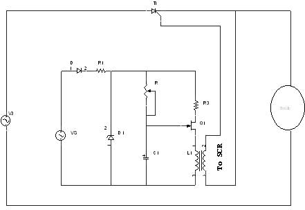
A unijunction transistor (UJT) is an electronic semiconductor device characterized by a single junction. It consists of three terminals: an emitter (E) and two bases (B1 and B2). The base is constructed from a lightly doped n-type silicon bar,...
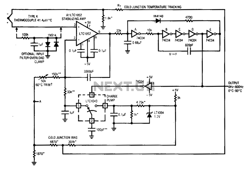
Al's positive input is biased by the thermocouple. Al's output drives a basic voltage-to-frequency (V-F) converter, which consists of 74C04 inverters and related components. Each V-F output pulse results in a fixed amount of charge being transferred from a...
This microphone preamplifier utilizes the low-noise integrated circuit (IC) uA739. It serves as a practical example of designing an effective preamplifier for dynamic microphones. The IC contains two identical integrated preamplifier circuits, with the second preamp functioning in the...
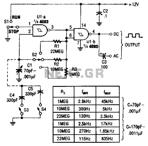
Two gates of a Quad 4093 are utilized in an astable multivibrator configuration. CI is a three-gang 365 pF variable capacitor with its sections connected in parallel. Additionally, S3 and S4 serve to switch in optional extra capacitors. The described...
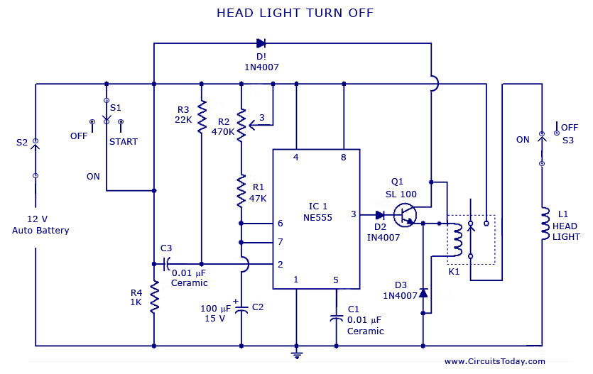
A circuit that can automatically turn off the headlights or lamps of a vehicle after a preset time. This light switching circuit is constructed using a 555 timer integrated circuit (IC). The described circuit utilizes the 555 timer IC in...
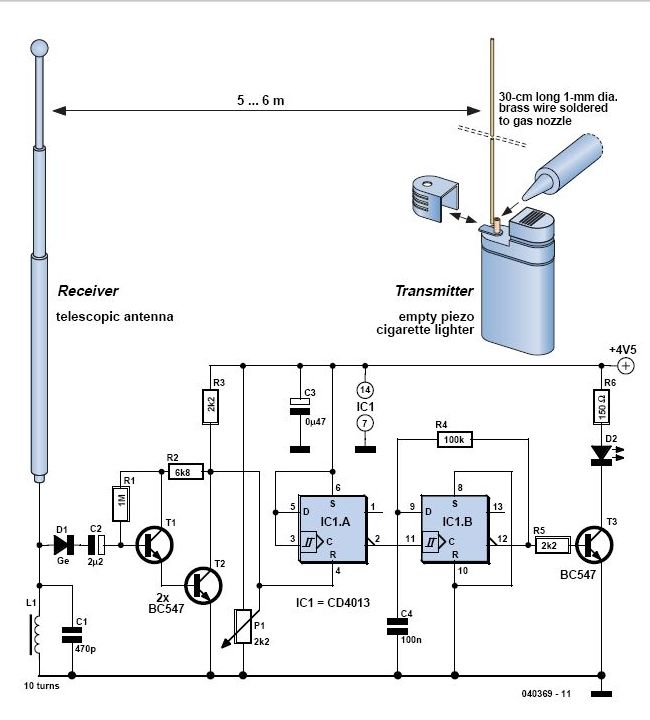
In 1896, Marconi successfully transmitted electromagnetic waves over a distance of approximately 3 kilometers. Shortly thereafter, he established radio communication across water between Lavernock Point in South Wales and Flat Holm Island. The transmitter utilized a spark inductor connected...