
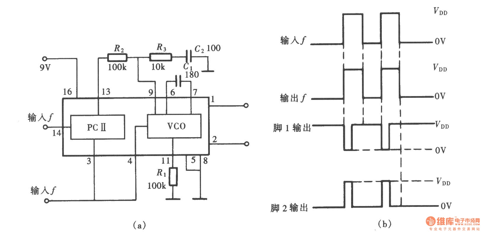
Frequency electronic locks LM567 schematic

The electronic lock circuit leverages the LM567 audio decoder's ability to detect specific frequencies, making it suitable for applications where secure access is required based on audio signals. The operation begins with an audio frequency oscillator that generates a specific frequency signal. This signal is fed into the LM567, which is configured to recognize that particular frequency.
When the input audio signal frequency aligns with the internal VCO's oscillation frequency, the LM567 produces a low output signal. This output can be utilized to trigger subsequent stages of the electronic lock mechanism. The output frequency decoder processes the signal from the LM567, ensuring that only the correct frequency will activate the lock.
Following the decoder, a driver circuit is employed to control the locking mechanism, which may include a relay or a transistor switch that physically engages or disengages the lock. The design of this circuit ensures that unauthorized frequencies will not trigger the lock, thus enhancing security.
Overall, the integration of the LM567 audio decoder into the electronic lock circuit provides a reliable method for frequency-based access control, with the potential for customization to accommodate various frequencies as needed for different applications. As shown in the frequency of electronic locks by the PLL audio decoder LM567 composition, the electronic lock circuit uses the LM567 audio decoding characteristic, that is, whe n it is consistent with the input signal frequency and the oscillation frequency of the internal VCO, it will output low. Circuit by an audio frequency oscillator, the output frequency decoder and driver circuit.
Related Circuits
The White's Classic I was a straightforward and user-friendly metal detector, making it suitable for entry-level enthusiasts. It featured a simple design with only an on/off switch and a discriminator adjustment knob. Although it lacked depth, it was capable...

This design circuit is for converting voltage to frequency. Typically, frequency meters are used in speed sensors, tachometers, and for measuring recurring signals. The frequency to voltage converter (FVC) can transform voltage into either a digital or analog tachometer....
A frequency signal tracking circuit is implemented using a phase-locked loop (PLL) configuration, which is a fundamental application of the CD4046 integrated circuit. The circuit, illustrated in the accompanying chart, utilizes the CD4046 to form a PLL that effectively...
The heart of the PWM Fan Controller is a PIC 12F675 microcontroller. This microcontroller is reading the analog output of a LM35 temperature sensor using a ADC (analog to digital converter). The resulting digital value is converted to a...
This is an integrated electronic mailbox circuit diagram designed for a front door. It activates when the door is opened. Additionally, when the cabinet photo detector is exposed to light, it will... The integrated electronic mailbox circuit is designed to...
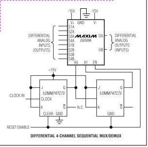
Maxim's DG508A and DG509A are monolithic CMOS analog multiplexers. The DG508A is a single 8-channel (1-of-8) multiplexer, while the DG509A is a differential 4-channel (2-of-8) multiplexer. Both devices guarantee high performance and reliability. The DG508A and DG509A analog multiplexers are...