
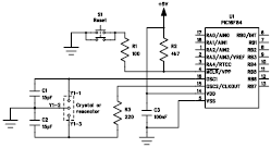
Crystal Oscillator with CMOS Inverter
The astable multivibrator circuit is designed to generate a continuous square wave output without requiring any external triggering. The CD4007 or MC14007 CMOS inverter provides the necessary logic levels to create the oscillation. This circuit configuration typically consists of two inverters connected in a feedback loop, where the output of the first inverter is fed into the second inverter.
The frequency of oscillation is primarily determined by the external resistors and capacitors connected to the circuit. The formula for calculating the frequency (f) can be expressed as:
f = 1 / (2 * (R1 + R2) * C)
where R1 and R2 are the resistances connected to the inverters, and C is the capacitance value of the timing capacitor. By adjusting these external components, the frequency can be varied, allowing for a wide range of applications, such as clock pulse generation, LED flashing, or tone generation in audio applications.
The circuit's power supply typically ranges from 3V to 15V, making it suitable for battery-operated devices. When implemented, the output can be taken from the second inverter, which provides a square wave signal. The high output impedance of the CMOS inverters allows for easy interfacing with other digital circuits, ensuring compatibility and versatility.
Overall, the astable multivibrator circuit using CMOS inverters is a fundamental building block in digital electronics, providing a reliable means of generating oscillatory signals for various applications.This is an astable multivibrator (oscillator) circuit using CMOS inverter. This circuit uses CD4007 or MC14007. This circuit has operating frequency range of.. 🔗 External reference
Related Circuits
This is a very simple circuit utilizing a 555 timer IC to generate a square wave of frequency that can be adjusted by a potentiometer. With values given, the frequency can be adjusted from a few Hz to several...
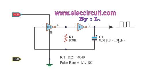
The inverter CMOS digital IC CD4049 is utilized to design a square wave oscillator generator. The CD4049 is a hex inverting buffer, which means it contains six independent inverters that can be used to generate square wave signals. This IC...
Although modern electrical appliances are increasingly self-powered, particularly portable devices used during camping or summer vacations, there are still occasions when a 230 V AC source is necessary. Additionally, it is beneficial for this source to operate at a...
Millimeter-wave frequency bands are appealing due to their wide available bandwidths. Signals can be generated in various ways; however, for each type of oscillator, electronic tuning of the source in a defined and controlled manner is desirable. Employing a...
The Bubba oscillator is another example of a phase shift oscillator. It utilizes a quad op-amp package to achieve a 45-degree phase shift. The Bubba oscillator is a type of phase shift oscillator that employs a configuration of operational amplifiers...
The following file contains detailed information about the design of a basic clock oscillator circuit diagram. Included in this file is information about selecting the components. The clock oscillator circuit is a fundamental component in various electronic systems, providing a...
Warning: include(partials/cookie-banner.php): Failed to open stream: Permission denied in /var/www/html/nextgr/view-circuit.php on line 713
Warning: include(): Failed opening 'partials/cookie-banner.php' for inclusion (include_path='.:/usr/share/php') in /var/www/html/nextgr/view-circuit.php on line 713