
optimize varactor tuned oscillators
Millimeter-wave oscillators are integral components in various high-frequency applications, including telecommunications, radar systems, and imaging technologies. The ability to electronically tune these oscillators allows for dynamic frequency adjustments, which is crucial for applications requiring precise frequency stability and adaptability. The use of varactor diodes in these oscillators enhances their performance by allowing for fine-tuning of the resonant frequency in response to varying DC voltages.
In practical applications, the design of a varactor-tuned oscillator involves careful consideration of the overall circuit topology, including the selection of inductors and capacitors that will work in conjunction with the varactor diode. The performance of the oscillator can be modeled using equivalent circuit representations that include the varactor's capacitance, the inductor's reactance, and any parasitic elements introduced by the physical layout and packaging of the components.
The tuning sensitivity of the oscillator is a critical parameter, as it defines how effectively the oscillator can respond to changes in the applied voltage. This sensitivity is influenced by the characteristics of the varactor diode, including its doping profile and the gamma parameter, which dictates the relationship between capacitance and voltage.
Furthermore, the physical construction of the varactor diode, including its mesa structure, affects its performance and reliability. Proper thermal management and shielding from external electromagnetic interference are also essential considerations in the design of millimeter-wave oscillators to ensure stable operation under varying environmental conditions.
In conclusion, the integration of varactor diodes into millimeter-wave oscillator designs provides a pathway for achieving high-performance, electronically tunable frequency sources that meet the demands of modern high-frequency applications.Millimeter-wave frequency bands are attractive for their wide available bandwidths. There are a number of ways to generate these signals but, for each type of oscillator, it is desirable to be able to tune the source electronically, as well as in a defined and controlled manner. By using a suitable reactive device (such as a varactor diode) for tuning these millimeter-wave oscillators,
the relationship between an applied voltage and the resulting frequency can be precisely defined. This can aid the design engineer in achieving the required spectral performance at these higher frequencies. Oscillators developed for use at millimeter-wave frequencies are typically designed around waveguide housings.
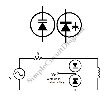
Electronic tuning of a waveguide-type oscillator can be accomplished in a number of ways, some of which are shown in Fig. 1. Additional information can be found in the technical literature (ref. 1) and in a recent article (ref. 2). The tuning sensitivity of a millimeter-wave varactor-tuned oscillator (VTO) can be estimated by means of relatively simple models, and this article hopes to provide some sights into the tuning relationship.
Usually, the approach is to keep the fixed capacity with the varactor diode as large as possible, using the varactor diode to control the resonant frequency to the greatest extent. A varactor diode is essentially an active device with positive-negative (PN) junction which has reverse bias applied.
This results in a movement of charge carried away from the junction, so that this region is referred to as the depletion layer. The depletion layer has charge on either side of the junction and acts like a parallel-plate capacitor (Fig.
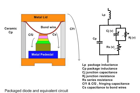
1). The capacitance relationship for a parallel-plate capacitor is C = µA/W, where: The typical fabrication process for a varactor diode results in a device with a mesa structure. This device can be mounted in a number of different standard and custom housings to simplify handling.
The junction capacitance and associated parasitic circuit elements can be included in a simple equivalent circuit (Fig. 3) for modeling and simulation purposes. The selection of a suitable semiconductor device for a varactor diode can make an impact on the performance of the diode, although this receives little coverage in the literature.
Varactors are true diodes with a clearly defined junction, which can be characterized by means of a particular doping profile; this is effectively captured in the gamma parameter for each varactor diode. The gamma parameter can be placed in two categories: abrupt and hyperabrupt. Quite simply, a varactor diode is effectively a variable reactance which is a function of some applied DC tuning voltage.
More detailed models of varactor diodes are available in the literature, which are useful for a specific package or unpackaged devices. To obtain a general understanding of a varactor diode`s behavior, it is a reasonable to ignore packaging and parasitic affects in the first instance, as this allows the designer to appreciate the merits of such devices.
For the basic resonant structure shown in Fig. 4, Cv is the varactor capacitance, Cd is the circuit capacitance, and L is the total inductance of the structure. This very simplistic approach provides a basic relationship between frequency and the applied voltage, with representing a doping constant, equal to 0.
5 for an abrupt diode and 1. 0 or 1. 25 for a hyperabrupt diode: In reality, it is difficult to achieve a diode capable of = 2. 0, although devices with values equal to 1. 0 and 1. 25 are commercially available. Figure 4 indicates the ideal behavior of frequency with voltage variation for a few varactor doping profiles. A more detailed analysis3 of a varactor`s influence on frequency tuning can be complicated. This is due to the issues of the varactor construction and device to device variation, as can be seen in Fig.
5. Package assembly and parasitic 🔗 External reference
Related Circuits
The circuit is an inverter configured as a linear amplifier. By incorporating a crystal and capacitors into the feedback path, the amplifier is transformed into an oscillator, enabling it to oscillate at or near the crystal's resonant frequency. Trimmer...
In a hybrid system, an analog system with digital control, voltage-controlled components are crucial as they can be interfaced with a Digital-to-Analog Converter (DAC) from the digital system. In hybrid systems, the integration of analog and digital components allows...
Although not intended for this application, a Hall-effect switch can be utilized as the foundation for an unconventional oscillator. The oscillator can be reconfigured, as illustrated in Fig. B, to enable the circuit's oscillating frequency to be regulated through...
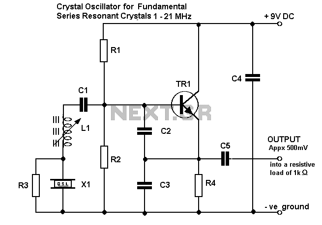
On following pages circuits are shown for 3rd overtone crystals 15 to 65MHz and 5th overtone crystals 60 to 105 MHz operating in their series resonant mode. In both of these circuits with the crystal short circuited, the oscillator...
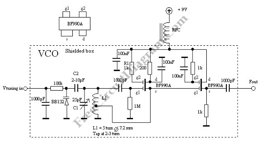
This is a Voltage Controlled Oscillator (VCO) circuit. This circuit is based on a Hartley oscillator. The frequency depends on the values of C1 and L1. The Voltage Controlled Oscillator (VCO) circuit described operates using a Hartley oscillator configuration, which...
A phase-shift audio oscillator exhibits excellent distortion characteristics due to "softened" diode limiting provided by the 1N914 diode and a resistor divider, along with degenerated gain facilitated by a 68-ohm emitter resistor. To minimize distortion, it is recommended to...
Warning: include(partials/cookie-banner.php): Failed to open stream: Permission denied in /var/www/html/nextgr/view-circuit.php on line 713
Warning: include(): Failed opening 'partials/cookie-banner.php' for inclusion (include_path='.:/usr/share/php') in /var/www/html/nextgr/view-circuit.php on line 713