
Crystal Radio III

The circuit described is a crystal radio receiver combined with an audio amplifier, designed to operate effectively in urban environments like Los Angeles. The radio utilizes a minimal antenna length of 15 feet, which is adequate for receiving strong AM radio signals. However, the selectivity of the circuit is affected by antenna length; longer antennas can enhance signal strength but may result in poorer selectivity, leading to interference from stronger stations.
The core of the radio consists of an inductor, constructed with 200 turns of #28 enameled copper wire wound around a 4-inch long PVC pipe with a diameter of 7/8 inch. This configuration yields an inductance of approximately 220 microhenries. The inductor features taps every 20 turns, allowing for flexibility in connecting the diode and antenna for optimal reception; the ideal connection point for the diode is found to be at 60 turns from the antenna end.
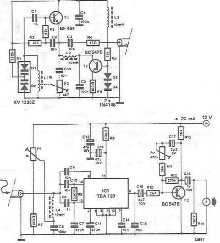
For demodulation, a germanium diode (preferably a 1N34A) is employed, though silicon diodes can also be utilized if the incoming signal strength is sufficient. The diode rectifies the RF signal, and a 300 picofarad capacitor is used to filter out the carrier frequency from the rectified output. The audio frequency signal is then passed through a 0.1 microfarad capacitor to the non-inverting input of the first operational amplifier (op-amp), which serves as a high-impedance buffer.
The second op-amp stage amplifies the audio signal by a factor of approximately 50. This stage is DC coupled to the first op-amp through a 10K resistor. It is essential to ensure that the paired 100K and 1 Meg resistors used in the circuit are closely matched (within 1% tolerance) to maintain proper operation. If the resistor values differ significantly, it may be necessary to use more closely matched resistors or to add a capacitor in series with the 10K resistor to stabilize the DC voltage at the transistor emitter, ideally keeping it in the range of 3 to 6 volts. Alternatively, reducing the overall gain can be achieved by using a smaller feedback resistor, such as 470K.
The circuit is designed to operate with high-impedance headphones, although standard walkman-style stereo headphones are also compatible. The entire circuit draws approximately 10 mA from a 9-volt power source, making it efficient and suitable for portable applications. Availability of components, such as the germanium diode, can be sourced from electronics retailers like Radio Shack.This is basically a crystal radio with an audio amplifier which is fairly sensitive and receives several strong stations in the Los Angeles area with a minimal 15 foot antenna. Longer antennas will provide a stronger signal but the selectivity will be worse and strong stations may be heard in the background of weaker ones.
Using a long wire antenna, the selectivity can be improved by connecting it to one of the taps on the coil instead of the junction of the capacitor and coil. Some connection to ground is required but I found that standing outside on a concrete slab and just allowing the long headphone leads to lay on the concrete was sufficient to listen to the local news station (KNX 1070).
The inductor was wound with 200 turns of #28 enameled copper wire on a 7/8 diameter, 4 inch length of PVC pipe, which yields about 220 uH. The inductor was wound with taps every 20 turns so the diode and antenna connections could be selected for best results which turned out to be 60 turns from the antenna end for the diode.
The diode should be a germanium (1N34A type) for best results, but silicon diodes will also work if the signal is strong enough. The carrier frequency is removed from the rectified signal at the cathode of the diode by the 300 pF cap and the audio frequency is passed by the 0.1uF capacitor to the non-inverting input of the first op-amp which functions as a high impedance buffer stage.
The second op-amp stage increases the voltage level about 50 times and is DC coupled to the first through the 10K resistor. If the pairs of 100K and 1 Meg resistors are not close in value (1%) you may need to either use closer matched values or add a capacitor in series with the 10K resistor to keep the DC voltage at the transistor emitter between 3 and 6 volts.
Another approach would be to reduce the overall gain with a smaller feedback resistor (470K). High impedance headphones will probably work best, but walkman stereo type headphones will also work. Circuit draws about 10 mA from a 9 volt source. Germanium diodes (1N34A) types are available from Radio Shack. 🔗 External reference
Related Circuits
For the shorter wavelength VHF and UHF bands, it is more practical to construct complex antennas such as a single-band Slim Jim or Yagis. Various projects include creating an electronic unit, as it is necessary for the Intermediate Level...
Liquid crystal displays (LCDs) are available in various versions and sizes. The wide variety of features has led to some confusion regarding pin configurations. Consequently, even after extensive searching for a suitable screen, users often encounter difficulties in utilizing...
A basic detector radio set that utilizes a vacuum tube instead of a crystal detector. This radio requires minimal components, and due to its inherent simplicity, it is easy to construct. Despite its simplicity, this receiver performs well when...
Superheterodyne receivers have been mass-produced since around 1924, but for reasons of cost did not become successful until the 1930s. Superheterodyne receivers represent a pivotal advancement in radio technology, characterized by their ability to convert high-frequency signals into lower...
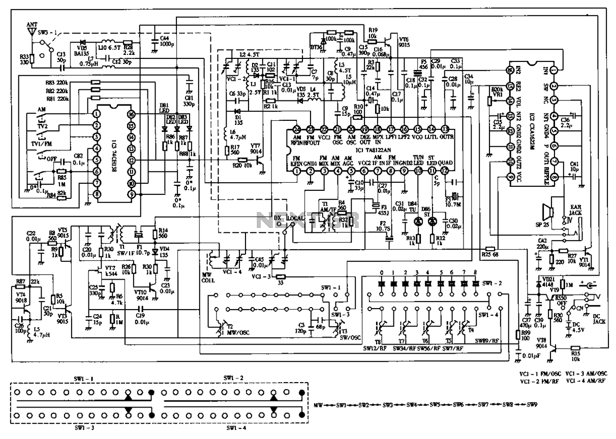
The circuit diagram for the Desheng 119 700 type FM, TV sound, medium wave, and short wave high sensitivity L2-band stereo radio is presented below. The Desheng 119 700 type radio circuit is designed to receive various frequency bands including...
The tuning stage of this long-wave and medium-wave radio receiver also functions as an active antenna, which can be optimally positioned for the best reception. The circuit is completely independent from the receiver, which includes a demodulator that provides...