
Crystal Tester

The crystal tester circuit is designed to accurately measure the frequency and quality factor (Q) of various crystal oscillators. The core of the tester typically consists of an oscillator circuit that utilizes a microcontroller or a dedicated frequency counter IC. This allows for precise frequency measurement, which is essential for determining the operational characteristics of the crystal under test.
The circuit board layout should be compact, ensuring that the crystal, which is usually mounted in a socket for easy replacement, is connected to the oscillator circuit with minimal parasitic capacitance. This is crucial for maintaining the integrity of the frequency measurement. The use of high-quality components, such as low-tolerance resistors and capacitors, will enhance the accuracy of the measurements.
In addition, the tester may include a digital display to show the measured frequency, along with additional indicators for the Q factor and possible fault conditions. User interface elements, such as buttons or a rotary switch, can be integrated to select different measurement modes or to calibrate the tester.
Power supply considerations are also essential; a stable voltage source, possibly using a voltage regulator, should be included to ensure consistent operation. Battery operation can be an option for portability, while a power jack can be provided for continuous use.
Overall, this crystal tester design aims to provide a reliable and user-friendly solution for evaluating crystal oscillators, making it suitable for both hobbyists and professionals in the electronics field.I needed to test some crystals for a project I was working on. I found lots of testers on the internet, but they all where lacking in one thing or another. I decided to take one of them and add the features that I wanted to it. This is the result. I also designed a small circuit board for it. 🔗 External reference
Related Circuits
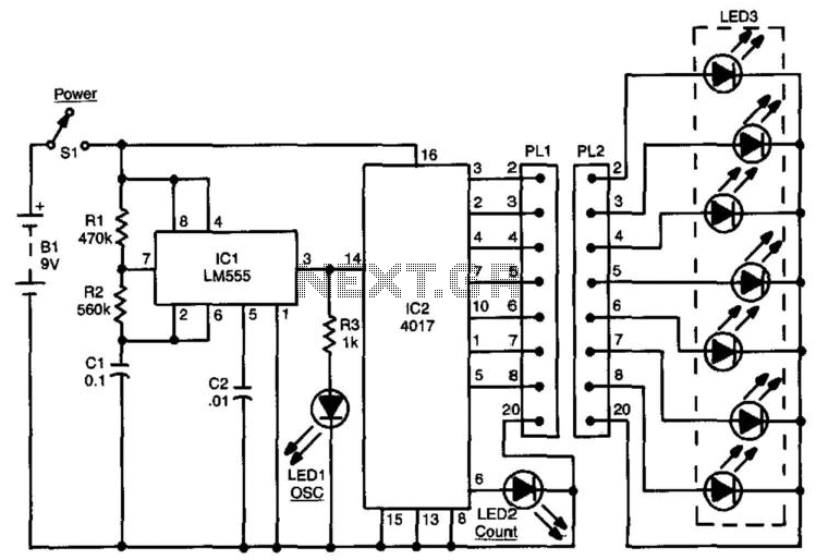
This circuit can be used to check up to an eight-conductor cable. IC1, a 555 timer, drives decade counter IC2, a 4017. Each LED should light in sequence. The cable to be tested is connected between PL1 and PL2....

A simple device that enables a quick check of common infrared remote controls can be beneficial for electronics enthusiasts often tasked with repairing or testing these widely used devices. A dependable circuit has been designed using a few components:...
An LCD essentially comprises two glass plates with a layer of liquid crystal material sandwiched between them. The LCD utilizes an electrically controlled light-polarizing liquid. The liquid crystal display (LCD) operates based on the manipulation of light through liquid crystals,...
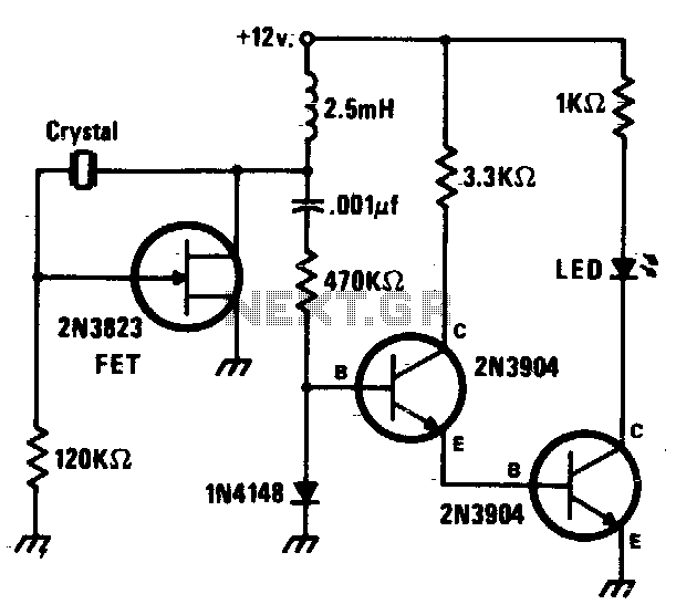
This circuit is a simple Pierce oscillator with an LED go/no-go display. The checker works best with crystals having fundamental frequencies in the seven to eight megahertz range. The Pierce oscillator circuit is a popular choice for generating high-frequency signals,...
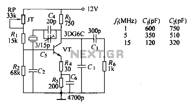
The typical crystal oscillator circuit depicted in the figure is a three-point oscillator designed for capacitance feedback. The oscillator's frequency is influenced by the series and parallel resonant frequencies of the crystal. This type of circuit is commonly known...
Determining whether a battery is empty or if there is a fault with a device can be challenging when a battery-powered device, such as a Walkman, fails to power on. Before seeking professional repair, it is advisable to test...