
LB1948M motor control driver electronic circuit design
The LB1948M motor driver IC is designed for efficient control of DC motors and stepping motors in various applications. It operates within a 12V power supply range, making it suitable for battery-operated devices and low-voltage systems. The low saturation voltage of 0.5V at a current output of 400mA ensures minimal power loss during operation, which is critical for enhancing the overall efficiency of the motor control system.
This motor driver supports multiple configurations, allowing for versatile applications. It can independently drive two DC motors, making it ideal for projects requiring simultaneous control of multiple motors. Alternatively, a single DC motor can be driven using a parallel connection, which can be beneficial in applications that require higher torque or where motor load sharing is necessary. Additionally, the IC is capable of driving a 2-phase bipolar stepping motor, providing flexibility for applications that require precise position control and variable speed operation.
The LB1948M features a zero-current draw in standby mode, which contributes to energy efficiency when the system is not actively driving motors. This feature is particularly advantageous in battery-powered applications, as it extends battery life by minimizing power consumption during idle periods. The braking function integrated into the driver allows for rapid deceleration of the motors, enhancing control and safety in applications where quick stops are required.
Moreover, the built-in thermal shutdown circuit protects the IC from overheating, ensuring reliable operation under varying load conditions. This feature is essential for maintaining the longevity and performance of the motor driver, especially in high-demand scenarios where motors may draw significant current.
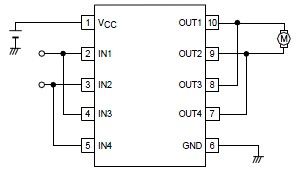
Overall, the LB1948M motor driver IC is a robust solution for forward-reverse motor control in various electronic projects, providing essential features and reliable performance for both hobbyist and professional applications.A very simple forward reverse motor control driver electronic circuit project can be designed using the LB1948M 2 channel low saturation voltage forward reverse motor control driver IC. LB1948M motor driver is optimal for motor drive in 12V system products and can drive either two DC motors, one DC motor using parallel connection, or a 2-phase bip
olar stepping motor with 1-2 phase excitation mode drive. Some features of the LB1948M motor driver IC are : 12V power supply, low saturation voltage: VO(sat) = 0. 5V (typical) at IO = 400mA, zero current drawn in standby mode, braking function, built-in thermal shutdown circuit.
🔗 External reference
Related Circuits
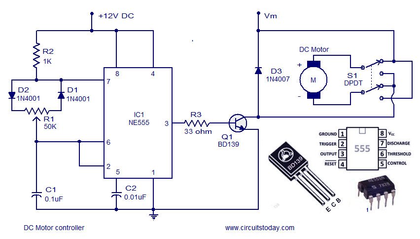
A DC motor controller based on an NE555 timer is presented here. The direction of rotation of the DC motor can also be changed using this DC motor speed control circuit. The described circuit utilizes the NE555 timer IC in...
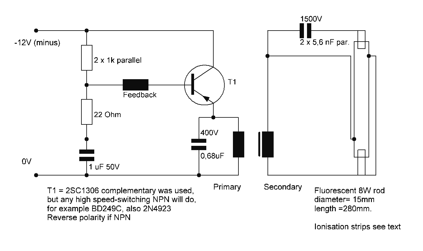
Starting a fluorescent lamp on an inverter can be challenging due to the trade-offs involved in achieving optimal operating efficiency with 12V drivers. Fluorescent lamps require a specific starting voltage to ionize the gas within the tube and initiate the...
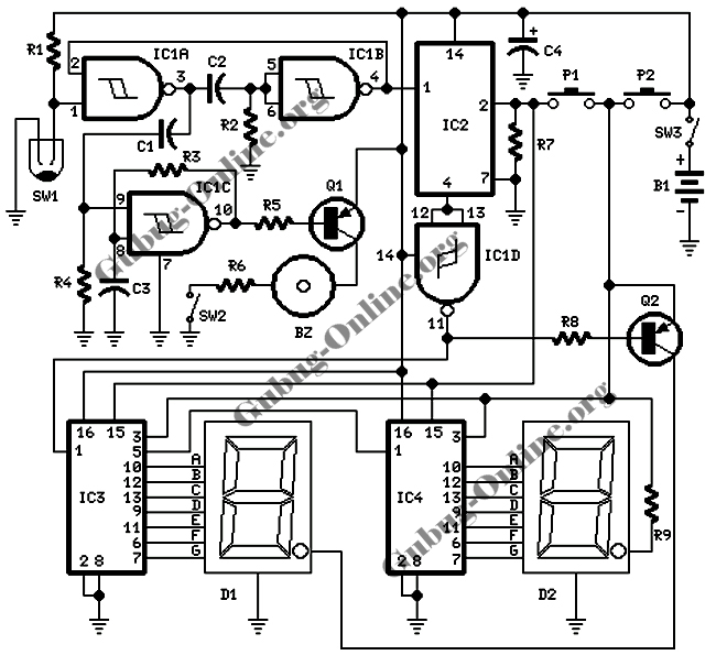
This design features a signal logic tester that utilizes a common cathode seven-segment display. The display indicates a logic level "1" (represented by an "H" on the display) or a logic level "0" (represented by an "L" on the...
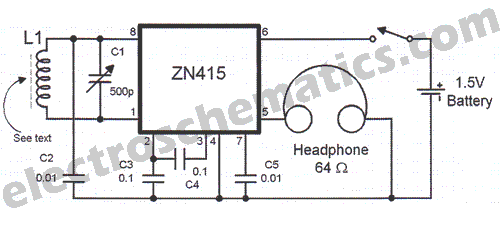
There are instances when a radio station can be found, and other times when no stations are detectable. The primary issue while tuning appears to be that any movement of the hands or body, such as releasing the tuning...
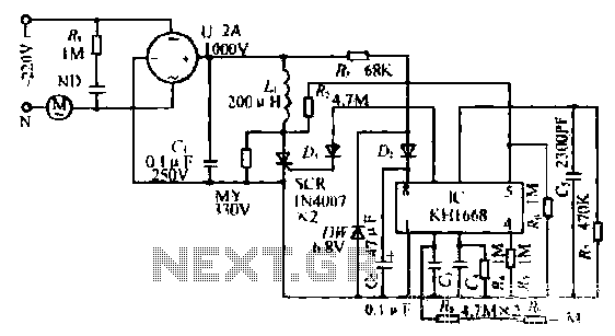
The synchronous vibration circuit operates with a control logic that includes three primary components. An internal oscillator is initiated by a synchronization pulse, transitioning to a low state immediately after the pulse. Upon power activation, the internal circuitry undergoes...
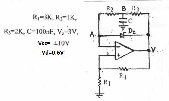
This circuit appears to be a Schmitt trigger oscillator. Based on the configuration of the resistors and capacitor, it is likely functioning as a sawtooth wave generator, with resistors R2 and R3 influencing the slope of the rising and...
Warning: include(partials/cookie-banner.php): Failed to open stream: Permission denied in /var/www/html/nextgr/view-circuit.php on line 713
Warning: include(): Failed opening 'partials/cookie-banner.php' for inclusion (include_path='.:/usr/share/php') in /var/www/html/nextgr/view-circuit.php on line 713