
Voltage Controlled Audio Mixer Circuit
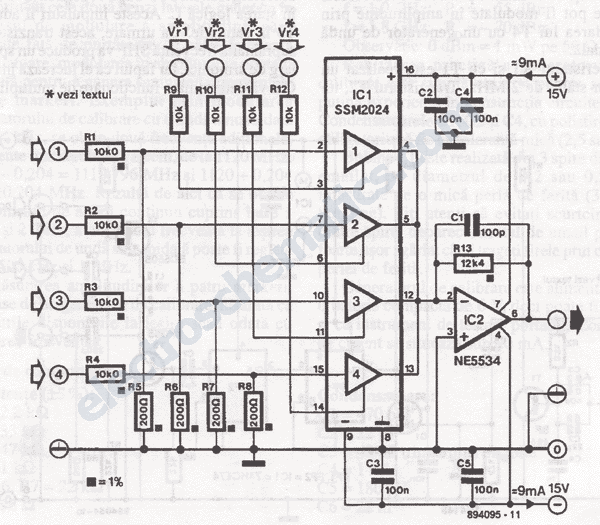
The audio mixer circuit utilizes the SSM2024 integrated circuit, which features low-noise, high-performance operational amplifiers suitable for audio applications. The SSM2024 is particularly advantageous due to its ability to provide high gain with minimal distortion, making it ideal for mixing audio signals from multiple sources.
In this schematic, each of the four amplifiers serves as a channel for audio input, allowing for the mixing of different audio signals. The configuration typically includes input resistors that set the gain for each channel, along with potentiometers to allow for adjustable volume control for each input.
The output of each amplifier can be fed into a summing stage, which combines the individual audio signals into a single output signal. This summing stage is essential for ensuring that the mixed audio maintains a balanced output level and clarity. Capacitors may be included in the output stage to block any DC offset, ensuring that only the AC audio signal is passed to the subsequent processing stages or to the output device.
Power supply considerations are also critical in this design. The SSM2024 requires a dual power supply, typically +15V and -15V, to operate effectively. Proper decoupling capacitors should be placed near the power pins of the IC to filter out any noise that may affect audio quality.
Overall, this audio mixer circuit schematic provides a robust solution for mixing multiple audio signals, leveraging the capabilities of the SSM2024 integrated circuit to achieve high fidelity and low distortion in the final output.This audio mixer circuit schematic we propose here is built around four amplifiers, which are current controlled, all of them incorporated in IC SSM2024, p.. 🔗 External reference
Related Circuits
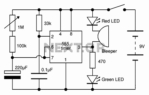
The Adjustable Timer circuit initiates timing upon activation. A green LED illuminates to indicate that timing is in progress. Once the designated time period elapses, the green LED turns off, the red LED activates, and an audible bleeper sounds....
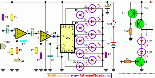
LED sequencer that follows the rhythm of music or speech, powered by a 9V battery, is a portable unit. The basic circuit illuminates up to ten LEDs in sequence, following the beat. The LED sequencer circuit operates by detecting audio...
Four application examples are presented in the figure, focusing on a three-phase brushless DC motor used in Winchester disk drives with an operating speed of 3600 RPM. Although the original design specifies an operating speed of 3600 RPM, alternative...
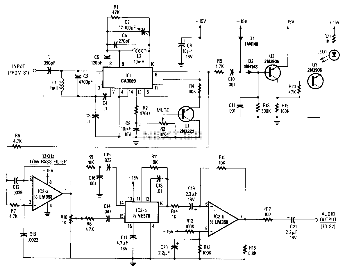
The baseband audio input originates from the pole of switch S1 in the stereo decoder and is coupled to IC1 (a CA3089) via a 78.6 kHz bandpass filter composed of capacitors C1 and C2, along with inductor L1. IC1...
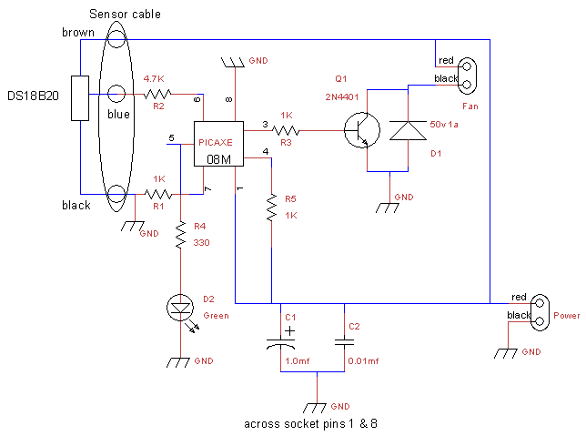
This is a fan controller designed for an audio/video cabinet. It utilizes a PICAXE 08M microcontroller and a DS18B20 temperature sensor. The fan activates at 30 degrees Celsius (approximately 86 degrees Fahrenheit) and deactivates at 28 degrees Celsius (around...
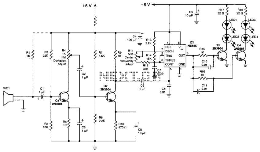
This transmitter employs a two-stage amplifier configuration using transistors Q1 and Q2 to frequency modulate an NE555 timer, which is set up as a voltage-controlled oscillator (VCO) operating at approximately 50 kHz. The resulting frequency-modulated pulse train is transformed...