
Cuckoo Sound Generator Circuit
The circuit operates by generating distinct audio frequencies that mimic the sounds of a cuckoo. The two-tone effect is achieved through a combination of oscillators, which are configured to produce two different frequencies. These frequencies are mixed to create the characteristic sound. The integrated audio amplifier is responsible for driving the loudspeaker, allowing the sound to be emitted at a sufficient volume for practical applications such as doorbells.
When the circuit is in free-running mode, it continuously cycles through the two tones, creating an ongoing cuckoo sound. This mode is useful for applications where a persistent sound is desired. Conversely, in one-shot mode, the circuit is triggered by a momentary press of switch P1, generating the two-tone effect once per activation. This feature is particularly useful for doorbell applications, where the sound is only needed upon pressing the button.
The circuit components include resistors, capacitors, and transistors that form the oscillating circuit, alongside the audio amplifier for sound output. The choice of values for these components will affect the frequency and quality of the sound produced. For external connections, the output can be taken from the capacitor C8, allowing for flexibility in how the sound is utilized, whether through additional amplification or recording.
Overall, this circuit provides a versatile solution for generating a recognizable and pleasant two-tone sound, suitable for various applications in electronic sound generation.This circuit generates a two-tone effect very much alike the cuckoo song. It can be used for door-bells or other purposes thanks to a built-in audio amplifier and loudspeaker. Used as a sound effect generator it can be connected to external amplifiers, tape recorders etc. In this case, the built-in audio amplifier and loudspeaker may be omitted and the output taken across C8 and ground.
There are two options: free running, when SW1 is left open, and one-shot, when SW1 is closed. In this case a two-tone cuckoo song will be generated at each P1 pressing.. 🔗 External reference
Related Circuits
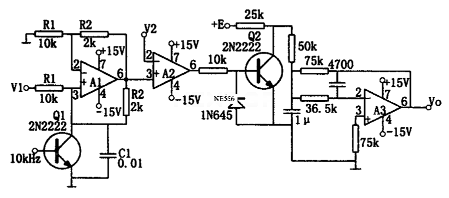
As illustrated in the dividing circuit diagram, A1 consists of a voltage-controlled current source, A2 functions as a voltage comparator, and A3 is configured as an active low-pass filter. When the time constant R1C1 is equal to the clock...
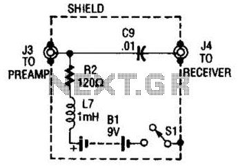
The purpose of the receiver/interface circuit is to pass RF to the receiver through capacitor C9, while adding DC power to the feedline through resistor R2 and RF choke L7. The receiver/interface circuit is designed to facilitate the transmission of...

In electronic technology, the triode utilizes a variety of general components and parts. The parameters of the triode and numerous electrical parametric measurement schemes are closely related to measurement results. Therefore, in electronic design, the base pin, typological judgment,...
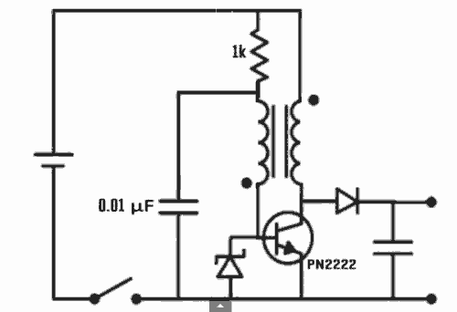
Excellent Joule thief circuit idea! The Joule Thief is a simple yet effective circuit designed to extract usable voltage from low-voltage power sources, such as depleted batteries. This circuit operates on the principle of boosting voltage through the use...
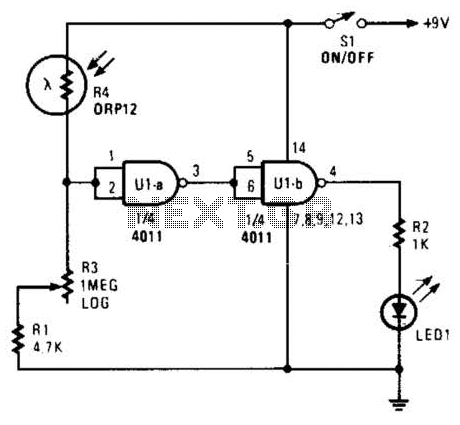
Two gates of a 4011 IC are utilized as a comparator. When the resistance of R4 decreases, the voltage at pins 1 and 2 increases, resulting in a logic zero at pin 3. This causes pin 4 to go...
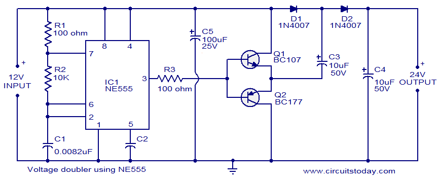
The circuit diagram of a simple voltage doubler using the NE555 timer is presented. In this configuration, the NE555 IC operates as an astable multivibrator at approximately 9 kHz. The bases of two transistors, Q1 and Q2, are connected...