
Enlarger Exposure Meter Circuit
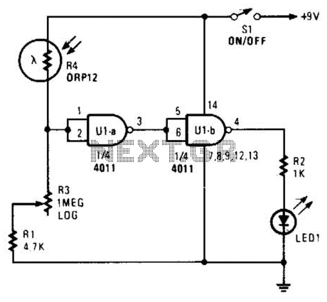
The described circuit employs two NAND gates from a 4011 quad NAND gate IC configured as a comparator, which effectively determines the light intensity based on the resistance of R4. The circuit operates by comparing the voltages at the inputs of the first NAND gate. As R4's resistance decreases, the voltage at the inputs (pins 1 and 2) rises, leading the output (pin 3) to transition to a low logic state (logic zero). This output change triggers the second NAND gate, causing its output (pin 4) to transition to a high state, which subsequently activates the LED.
In this configuration, R3 serves as a variable resistor or potentiometer, allowing for calibration based on the desired exposure time or light intensity. The calibration process involves adjusting R3 until the LED toggles at the threshold of ON/OFF, signifying the appropriate light level for exposure. The calibration can be performed using a known enlarger and a standard photographic negative, ensuring that the system can accurately indicate when the light is sufficient for correct exposure of photographic prints.
To enhance the functionality of this circuit, it may be beneficial to incorporate additional components such as a capacitor for signal smoothing or a transistor for driving larger loads, depending on the application requirements. Additionally, implementing a feedback mechanism could allow for more precise control over the exposure time by automatically adjusting R3 based on real-time light conditions. Overall, this comparator circuit is a practical solution for light measurement in photographic applications, providing a visual indication through the LED when optimal exposure conditions are met. Two gates of a 4011 arc used as a comparator. When the resistance of R4 decreases the voltage at pin 1 and 2 increases, producing a logic zero at pin 3, causing pin 4 to go high and activating the LED. R3 is calibrated in light units, or seconds exposure time. To calibrate, set pot R3 so as to just be on the LED ON/OFF threshold. With a light level that is suitable to correctly expose a photographic print, use a known enlarger and a known negative. 🔗 External reference
Related Circuits
A phase control circuit can be utilized to regulate the power supplied to an AC load. This circuit modulates the AC waveform by cutting portions of the cycle. A phase control circuit is an essential component in various applications where...

A useful marker oscillator can be constructed using an NE555 timer to generate pulses at an audio frequency. This design facilitates the detection of the signal even amidst interference. The crystal frequency can range from 1 to 30 MHz. The...
The schematic represents a water level alarm circuit. This circuit functions as a water level sensor and emits a melodious alarm sound when the two probes within the circuit detect the presence of water. This water level indicator circuit...
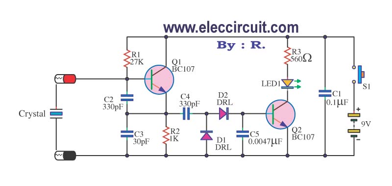
A multimeter cannot be used to test a crystal oscillator. Instead, a dedicated circuit is required, capable of checking crystals within the frequency range of 100 kHz to 900 MHz. This circuit is easy to construct and cost-effective. To construct...

An AC-coupled unity gain voltage follower operating on a single supply is illustrated. The voltage divider network consisting of resistors R1 and R2 provides a DC voltage equal to half the supply voltage to the non-inverting input of the...
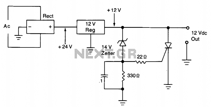
The silicon controlled rectifier (SCR) is designed to handle at least the current provided by the power supply. It is connected in parallel across the 12 V DC output lines but remains inactive until a voltage is applied to...
Warning: include(partials/cookie-banner.php): Failed to open stream: Permission denied in /var/www/html/nextgr/view-circuit.php on line 713
Warning: include(): Failed opening 'partials/cookie-banner.php' for inclusion (include_path='.:/usr/share/php') in /var/www/html/nextgr/view-circuit.php on line 713