
Current and Variable Voltage Power Supply

The described circuit utilizes operational amplifiers (op-amps) to manage a bipolar power supply, specifically designed for precision applications requiring a stable output voltage that can be adjusted down to zero. The op-amps operate on a dual supply voltage of +/- 8 volts, providing the necessary headroom for accurate signal processing. The circuit employs a feedback mechanism where the output current is monitored through a low-value resistor, enabling real-time adjustments to maintain a constant current output.
The 500-ohm potentiometer serves as a variable resistor to fine-tune the reference voltage applied to the op-amp's non-inverting input. The feedback loop ensures that as the load current increases, the op-amp adjusts the base voltage of the 2N3053 transistor, which acts as a driver for the larger 2N3055 power transistor responsible for delivering the load current. This configuration allows the circuit to maintain a steady output current despite fluctuations in load conditions.
The inclusion of TIP32 and 2N3055 transistors necessitates proper thermal management due to the significant heat generated during operation. The power dissipation is calculated based on the voltage drop across the transistor and the load current, emphasizing the importance of selecting appropriate heat sinks to prevent thermal overload. The 0.2-ohm current sensing resistor is critical for accurate current measurement and should be rated adequately to handle the expected power dissipation without failure.
The design also incorporates a switch to adjust the input voltage, providing flexibility in managing thermal performance. By selecting different voltage settings, the circuit can adapt to various load conditions while optimizing heat generation, thereby enhancing reliability and longevity of the components involved. Overall, this circuit exemplifies a robust solution for applications requiring precise current control and efficient thermal management in power supply systems.Another adjustment of application opamps to adapt a ability accumulation is apparent below. The ability agent requires an added ambagious to accumulation the op-amps with a bipolar voltage (+/- 8 volts), and the abrogating voltage is additionally acclimated to accomplish a advertence voltage beneath arena so that the achievement voltage can be ada pted all the way bottomward to 0. Accepted attached is able by analysis the voltage bead beyond a baby resistor placed in alternation with the abrogating accumulation line. As the accepted increases, the voltage at the wiper of the 500 ohm pot rises until it becomes according or hardly added absolute than the voltage at the (+) ascribe of the opamp.
The opamp achievement again moves abrogating and reduces the voltage at the abject of the 2N3053 transistor which in about-face reduces the accepted to the 2N3055 canyon transistor so that the accepted stays at a connected akin alike if the accumulation is shorted. Accepted attached ambit is about 0 - 3 amps with apparatus shown. The TIP32 and 2N3055 canyon transistors should be army on acceptable calefaction sinks and the 0. 2 ohm accepted analysis resistor should be rated at 2 watts or more. The calefaction produced by the canyon transistor will be the artefact of the aberration in voltage amid the ascribe and output, and the amount current.
So, for archetype if the ascribe voltage (at the beneficiary of the canyon transistor) is 25 and the achievement is adapted for 6 volts and the amount is cartoon 1 amp, the calefaction blown by the canyon transistor would be (25-6) * 1 = 19 watts. In the ambit below, the about-face could be set to the 18 volt position to abate the calefaction generated to about 12 watts.
🔗 External reference
Related Circuits
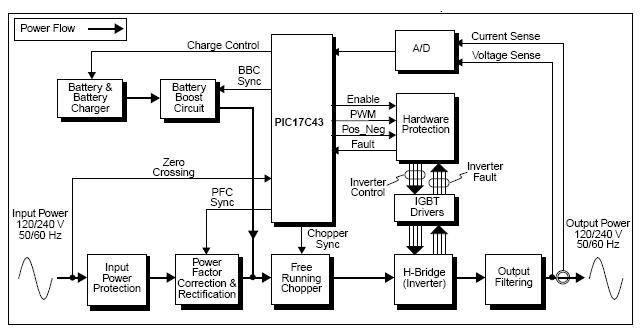
The UPS (Uninterruptible Power Supply) Reference Design offers a pre-designed uninterruptible power supply solution utilizing the flexibility of the PIC17C43 microcontroller. This microcontroller is noted for its low-cost and high-performance capabilities, which are not typically found in other microcontrollers....

This document presents a basic electronics project focused on creating a regulated power supply. A regulated power supply is essential for various electronic circuits, as it provides a constant voltage necessary for their operation. Understanding how to construct a...
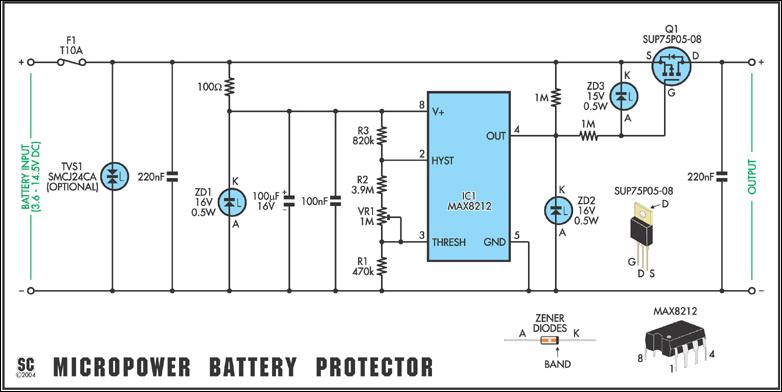
In May 2002, Silicon Chip introduced the "Battery Guardian," a project aimed at safeguarding 12V car batteries from over-discharge. This unit has gained significant popularity and remains available from kit suppliers. The new design does not replace the Battery...
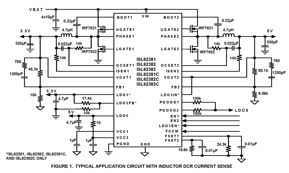
The ISL62381, ISL62382, ISL62383, ISL62381C, ISL62382C, and ISL62383C family of controllers generate supply voltages for battery-powered systems. These controllers include two pulse-width modulation (PWM) controllers, adjustable from 0.6V to 5.5V, and two linear regulators, LDO5 and LDO3, that generate...
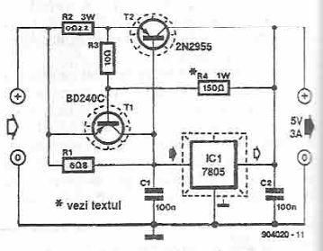
This power supply circuit is designed to provide a high current 5-volt output using a 7805 voltage regulator along with several standard electronic components. The transistor T1 functions as a current limiter. When the voltage across resistors R2 and...
The circuit depicted in the figure is a limiting protection charger. The VT transistors and resistor R3 create a limiting network. As illustrated, resistor R3 is connected in series with the battery being charged, acting as the emitter resistor...