
Current Dimmer for white 24 LED array
The battery pack can be 4 AA, C, or D size Alkaline, Ni-Cad, NiMH, 1.5V AA Lithium cells, or a 6V Lead-Acid. Three-cell C or D alkaline packs should also work, but they will not be discharged as deeply. "Dead" cells from halogen lamps, GPS, etc., should give hours of "free" light at lower current settings. The latest pack is two 3V, 8AH lithium cells removed from a military surplus BA-5598/U battery. These are available from Fair Radio Sales. The headpiece is an old waterproof "Easter Seals" Lexan "Roosa" light with a rocker on-off switch. The red model HL-4AA with a 4AA pack on its headband is available. All the parts are available separately, including the headpiece, battery packs, and replacement lenses. They also sell a complete headlamp with a halogen bulb (and spare) with a microtroller switching voltage regulator (not suitable for LEDs).
A 24-LED parallel array can be purchased from HDS systems. The Nichia LEDs have a 20-degree half-power beam width with significant sidelight, which seems ideal. The simplest way to obtain premium Nichia LEDs is to order directly from Nichia. The part number is NSPW500BS. The cost is $2.05 each for a quantity of exactly 100. Smaller quantities are too expensive, and sorting by voltage drop from a larger batch is necessary.
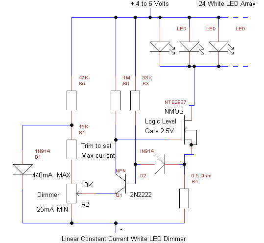
The circuit includes a MOSFET current source that can be any N-channel enhancement mode unit designed to be driven by "logic level" signals. It must fully turn on at 400mA with Vgs<3V. A small 1" square of sheet aluminum serves as a heat sink. Dissipation is about 0.9 watts at maximum current with a true 6V worst-case source. R4 samples the LED current, with a voltage drop of 0.2V at 400mA. If a larger or smaller array is used, R4 should be adjusted to give a ~0.2V drop at maximum array current (~20mA/LED).
Q1, D2, R3, and R6 form a simple "single supply" op-amp that can sense the voltage across R4 nearly down to zero volts. The forward voltage drop across D2 is nearly identical to the base-emitter drop of Q1, thus the voltage between the arm of R2 and ground is the same as the voltage across R2. D2 provides nearly perfect temperature compensation for the dimmer control, which becomes critical at the dimmest settings. R5 and D1 provide a regulated voltage for the dimmer control R2. This voltage, about 0.5V, is not temperature compensated but is not critical in this design.
When R2 is set to maximum current, 0.2V will appear on the base of Q1. The collector current of Q1 will be momentarily cut off, turning on the MOSFET. The voltage across R4 will rise until it reaches 0.2V, giving an array current of 400mA. Q1 will then turn on, regulating the array current. R1 is the only critical part; it must be chosen to provide the desired maximum array current at the maximum setting of R2.This simple Linear circuit provides continuously variable regulated current (~25-400mA) from a 4-6 Volt source. I chose a linear design for simplicity, reliability, ease of repair, and to avoid switching EMI in my Cave Radios.
The circuit requires only 0.2V headroom above the parallel LED Array voltage to provide regulation at maximum current. The headroom stays low until the LED's are extinguished at about 0.75V/cell for 4-cell packs. End of life for alkalines is usually considered to be 0.9V/cell. My HDS 24-LED array requires 2.9V at 25mA and 3.5V at 440mA. The circuit can be scaled for larger or smaller arrays, and should actually handle several Amps with a larger heatsink. With 4 AA Alkalines, life should be 3 hours (or more) at maximum setting for a 24-LED array, but ~60-80 hours at minimum setting, which is bright enough for many activities, including reading, if the mounting bracket allows the lamp to pivot downward like mine does.
In a two week test, I found that the white even light made caving easy. The "rings" and sharp cutoff of halogen lamps are absent. I found that I could usually get away with 200mA when moving, and much less when stationary (surveying, resting, eating), getting up to a10 hour trip from 4 AA's. The real beauty of white LED's is that the light remains white even at the lowest settings, compared to halogen light which shifts rapidly to infrared when dimmed.
The battery pack can be 4 AA, C, or D size Alkaline, Ni-Cad, NiMH, 1.5V AA Lithium cells, or a 6V Lead-Acid. 3-cell C or D Alkaline packs should also work, but they will not be discharged as deeply. "Dead" cells from Halogen lamps, GPS, etc., should give hours of "free" light at lower current settings.
My latest pack is two 3V, 8AH lithium cells removed from a military surplus BA-5598/U battery (5 cells/battery). These are available from Fair Radio Sales at http://www.fairradio.com at 2 for $6.50 plus shipping. My headpiece is an old waterproof "Easter Seals" Lexan "Roosa" light with a rocker on-off switch. See http://www.lightingpro.org (under construction), but you can call them directly (860-728-1061 in CT) or email [email protected].
The red model HL-4AA with a 4AA pack on its headband is $20. All the parts are available separately, including the headpiece, battery packs, and replacement lenses. They also sell a complete headlamp with halogen bulb (and spare) with Willy Hunt's microtroller switching voltage regulator (not suitable for LED's) for $55 retail, but maybe at $45 if you are worthy.
Because I am lazy, I purchased a 24-LED parallel array from Henry Schneiker of HDS systems at http://www.hdssystems.com or 1-877-437-7978 (toll free). If you are a caver, he might be willing to sell you enough LEDs for a light at reasonable cost, but remember that they must be matched for this parallel array.
The Nichia LED's have a 20 degree half power beamwidth with significant sidelight, which seems ideal. The simplest and surest way to get premium Nichia LEDs is to order directly from http://www.nichia.com .
The part number is NSPW500BS (20 degree, 6800 mcd, 5 mm dia, flange). The cost is $2.05 each for a quantity of exactly 100, plus $8.00 for prompt shipping. Smaller quantities are way too expensive, and you need to sort them by voltage drop (at 20 mA) from a larger batch anyway. See Garry Petrie's "Perfect LED Light" at http://home.europa.com/~gp/perfect_led_light.htm for detailed technical info on white LED's and a simple way to assemble an LED array on a do-it-yourself circuit board.
He shows how to install arrays into Petzl Micro and Mega headlamps using switching regulators. However, the regulators themselves are constant voltage rather than the desired constant current, and are the lamps truly submersible? An excellent Website. Another resource is the LED Flashlight Page, http://www.uwgb.edu/nevermab/led.htm. See Ray Cole's Website, http://members.cox.net/k4gaa/caving.htm, for info on a 24 LED light using a series-parallel arrangement to nearly eliminate matching, and an efficient dimmable switching regulator.
I used a commercial array because of the careful voltage matching required in order to obtain anywhere near equal light from each LED when they are wired in parallel (and avoid overheating at full power). I would have to had purchase a large quantity of LED's to solve this problem. This was expensive, but was the only real cost. The MOSFET current source can be any N-channel enhancement mode unit designed to be driven by "logic level" signals.
It must fully turn on at 400mA with Vgs<3V. Beware of static electricity on the gate of this unit! I destroyed the IRLZ34N used in the breadboard when I soldered it into the actual unit. A small 1" square of sheet aluminum serves as a heat sink. Dissipation is about 0.9 watts at maximum current with a true 6V worst case source. R4 samples the LED current. Voltage drop is 0.2V at 400mA. If a much larger or smaller array is used, R4 should be adjusted to give ~0.2V drop at maximum array current (~20mA/LED). Q1, D2, R3, and R6 form a simple "single supply" op-amp that can sense the voltage across R4 nearly down to zero volts.
The forward voltage drop across D2 is nearly identical to the base-emitter drop of Q1, thus the voltage between the arm of R2 and ground is the same as the voltage across R2. D2 provides nearly perfect temperature compensation for the dimmer control, which becomes very critical at the dimmest settings.
R5, and D1 provide a regulated voltage for the dimmer control R2. This voltage, about 0.5V, is not temperature compensated, but is not critical in this design. If R2 is set to max current, 0.2V will appear on the base of Q1. The collector current of Q1 will be momentarily be cut off, which will turn on the MOSFET. The voltage across R4 will rise until it reaches 0.2V, giving an array current of 400mA. Q1 will then turn on, regulating the array current. R1 is the only critical part. R1 must be chosen to provide the desired maximum array current at the maximum setting of R2. 🔗 External reference
Related Circuits
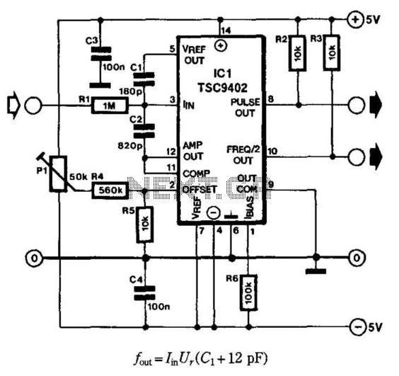
Teledyne Semiconductor's Type TSC9402 IC is highly suitable as an economical current-to-frequency converter. The maximum input current for the design depicted in the diagram is 10 mA (input voltage range is 10 mV to 10 V), while the output...

This LED VU Meter (volume unit) is designed to monitor and display power levels present at the speaker terminals of a stereo audio power amplifier. The levels are represented in ten discrete steps using ten LEDs for each channel,...
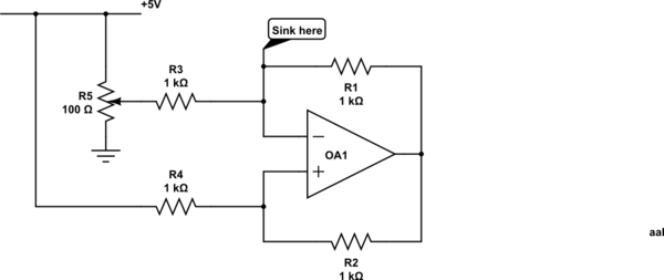
Control a current through several current-mirror devices (specifically the IREF pin on the TLC5940) using a single potentiometer. A modified Howland current source has been utilized, which works adequately with the specified resistor values for dimming an LED. However,...

This circuit is a simple remote-controlled relay capable of switching lamps or other devices. D1 can be a phototransistor, LDR, or an infrared transistor. The circuit is controlled using an IR remote, similar to a TV remote control, when...
The full wave phase control circuit below was found in a RCA power circuits book from 1969. The load is placed in series with the AC line and the four diodes provide a full wave rectified voltage to the...

Most LED driver circuits utilize a series resistor to regulate the current flowing through the LED. This method is optimal for applications that require only a few LEDs. However, for applications involving many LEDs, this approach becomes inefficient, leading...