
Lamp Dimmer schematic
The circuit operates as a phase control dimmer for AC loads, utilizing a full-wave rectification approach to manage power delivery. The four diodes are arranged in a bridge configuration, ensuring that regardless of the AC polarity, the load receives a rectified voltage, which is critical for the SCR's operation. The SCR (Silicon Controlled Rectifier) serves as a controlled switch that allows current to flow through the load once it is triggered by the gate signal.
The timing mechanism is pivotal for controlling the phase angle at which the SCR is turned on. The capacitor (2.2 µF) charges through the 50K potentiometer, and once the voltage across it reaches approximately 8 volts, the small signal transistors switch on. This action discharges the capacitor into the gate of the SCR, turning it on and allowing current to flow through the load for the remainder of the AC cycle.
The adjustment of the 50K potentiometer directly influences the charge time of the capacitor. A lower resistance allows the capacitor to charge faster, thereby triggering the SCR earlier in the AC cycle, which increases the average voltage applied to the load. Conversely, increasing the resistance delays the SCR's triggering, resulting in a lower average voltage across the load.
Furthermore, the 15K resistor serves as a calibration tool, allowing for fine-tuning of the output voltage when the 50K potentiometer is set to its maximum. This feature is essential for ensuring the circuit can accommodate variations in component tolerances, enabling the user to achieve the desired performance without compromising safety or functionality.
It is critical to observe safety precautions when working with AC circuits, as they can pose significant electrical hazards. Proper insulation and handling practices must be followed to prevent accidental contact with live components.The full wave phase control circuit below was found in a RCA power circuits book from 1969. The load is placed in series with the AC line and the four diodes provide a full wave rectified voltage to the anode of a SCR. Two small signal transistors are connected in a switch configuration so that when the voltage on the 2.2uF capacitor reaches about 8 volts, the transistors will switch on and discharge the capacitor through the SCR gate causing it to begin conducting.
The time delay from the beginning of each half cycle to the point where the SCR switches on is controlled by the 50K resistor which adjusts the time required for the 2uF capacitor to charge to 8 volts. As the resistance is reduced, the time is reduced and the SCR will conduct earlier during each half cycle which applies a greater average voltage across the load. With the resistance set to minimum the SCR will trigger when the voltage rises to about 40 volts or 15 degrees into the cycle.
To compensate for component tollerances, the 15K resistor can be adjusted slightly so that the output voltage is near zero when the 50K pot is set to maximum. Increasing the 15K resistor will reduce the setting of the 50K pot for minimum output and visa versa.
Be careful not to touch the circuit while it is connected to the AC line. 🔗 External reference
Related Circuits
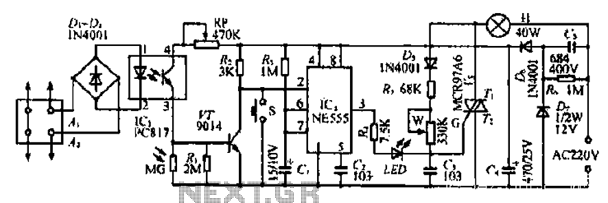
The Ai. A2 series operates with a telephone line, where sound anomalies or off-hook currents activate a light within an arc tube, which in turn triggers a photosensitive MOSFET. This process involves a saturated conduction base voltage that sends...
The primary objective of this design was to address a minor flaw in the widely used Fridge Door Alarm circuit, which has been available on this website since 1999 and has been constructed by numerous hobbyists. This circuit ceases...
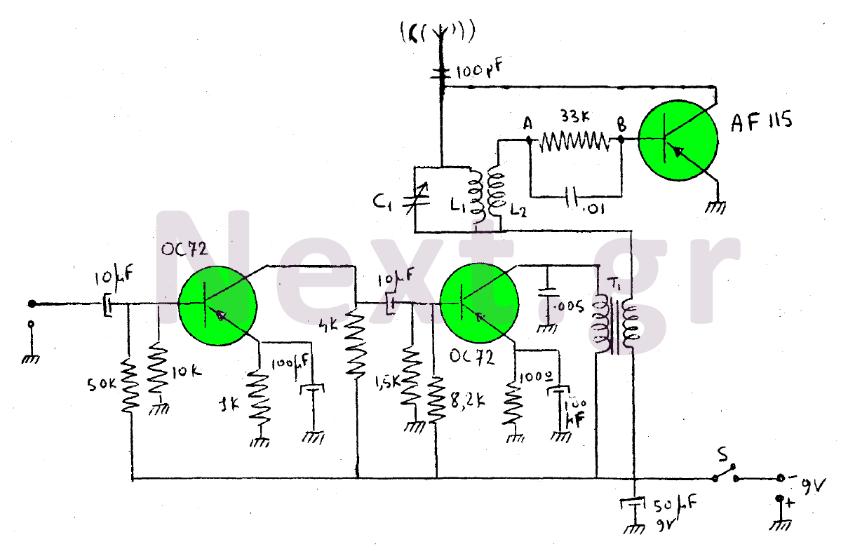
This device is a transmitter operating on medium-wave and short-wave frequencies, utilizing three transistors. The AF115 transistor serves as the oscillator within the circuit. The low-frequency amplifier, consisting of two OC72 transistors, functions as the modulator that generates the...
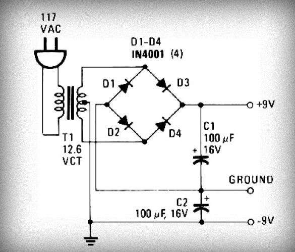
Initially, voltage from AC 220V or 110V enters the transformer, which reduces it to 12V AC. This AC voltage is then rectified using either four diodes or a bridge rectifier to convert it to DC voltage. The resulting DC...
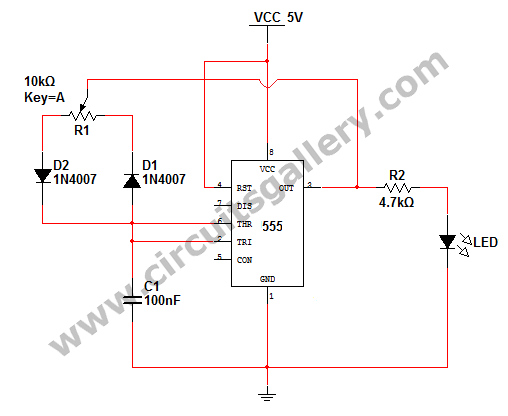
How to change the brightness of an LED. Are LED lights dimmable? Is it possible to adjust the brightness of LEDs? An LED is essentially a diode; when the forward voltage exceeds 0.7 volts, it begins to emit light,...
24V DC is a widely used voltage in industrial environments. The circuit illustrated below is designed to accept four different 24V DC alarm input signals, which are utilized to activate a single low-power beeper. The beeper is a magnetic...