
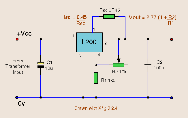
Current Limiting Power Supply

This power supply unit is designed to provide a reliable and adjustable voltage output while incorporating essential safety features through current limiting. The adjustable voltage range from 3V to 24V caters to various applications, making it versatile for both experimental and practical uses in electronic projects. The inclusion of a current limiting feature not only protects the connected load but also the power supply itself from potential damage due to overcurrent situations.
The selection switches (SW1, SW2, and SW3) enhance user control over the operation of the PSU. SW1 enables the user to toggle between two voltage ranges, effectively optimizing the efficiency of the heatsink by minimizing unnecessary heat generation during low voltage operations. SW2 allows for flexible current limiting, accommodating different project requirements. The values set by resistors R4, R5, and R6 can be adjusted to meet specific needs, ensuring that the PSU can be tailored for various applications.
The design of the heatsink is crucial for maintaining optimal operating temperatures, particularly when the unit is under load. The dimensions specified ensure adequate thermal dissipation, which is essential for preventing overheating and maintaining the longevity of the components. The recommendation for a well-ventilated housing further supports effective thermal management.
The front panel serves not only as a user interface but also as a wiring guide, allowing users to create their own layouts based on individual preferences or space constraints. The adaptability of the L200C component, despite its non-standard pin spacing, demonstrates the design's flexibility and encourages users to engage in hands-on assembly.
Overall, this 1-amp variable-voltage PSU is a robust tool for electronic experimentation and development, combining adjustable voltage and current limiting features in a user-friendly design.This is a 1-amp variable-voltage PSU. It adjusts from about 3v to 24v: and has the added feature that you can limit the maximum output current. This is invaluable when (for example) you power-up a project for the first time or soak-test a piece of equipment.
SW3 is the on/off switch. It also lets you choose between the output with the current limi t and the one without. SW2 provides a selection of three different limits. You can increase or decrease this number if you wish. The limits are fixed by R4, R5 & R6. They are set at 10mA, 25mA & 65mA respectively; but you can choose whatever limits you like. If you try to draw a current above the limit you`ve selected, the output voltage will fall. Thus, the voltmeter indicates when the load on the output is excessive. The housing should be well ventilated. The heatsink is a folded strip of aluminium about 2mm thick, 18cm long and 6cm tall. SW1 allows you to choose between the (3v to 12v) and (3v to 24v) outputs. This reduces the power the heatsink has to dissipate when the output voltage is low. The drawing of the front panel is intended mainly as a wiring diagram - you can choose your own layout. The pin spacing of the L200C doesn`t suit the stripboard; but with a little persuasion it can be made to fit.
Since the limiting resistors may have a relatively low value, a few ohms between the contacts of the wafer-switch will have a significant effect. If (with time) you find that the limits have fallen, use a spray-cleaner on the switch. 🔗 External reference
Related Circuits
The versatile 5 pin L200C regulator offers both voltage and current regulation in a single package. The IC also features thermal shutdown and input over voltage protection up to 60 Vdc. The package is also available as L200CV which...
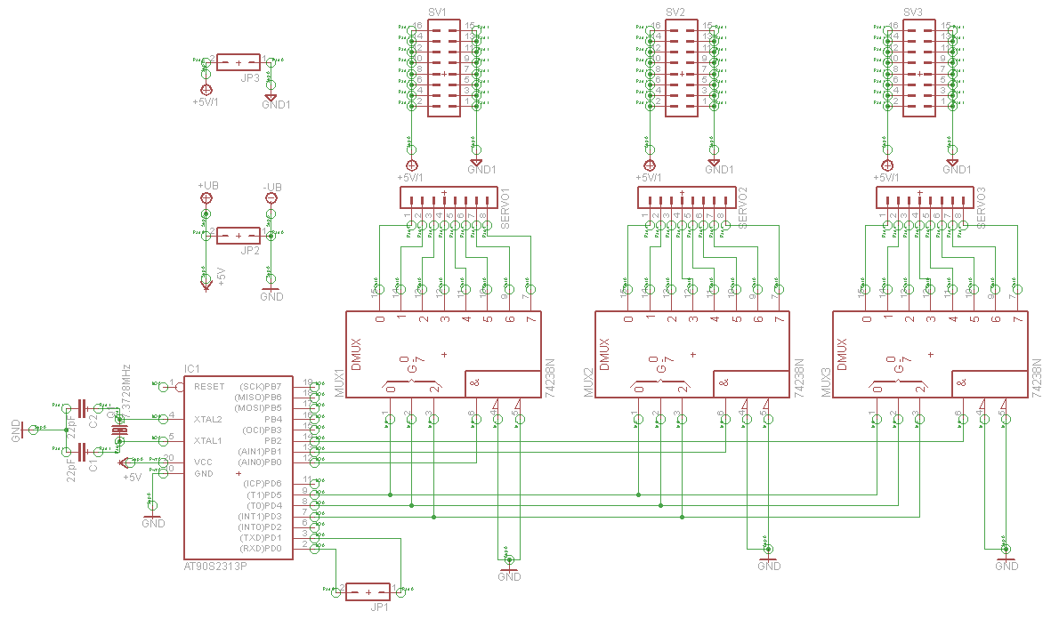
A serial servo controller is being developed to enhance knowledge of electronics and assembly language as part of a hexapod robot project. Initially, the ATTiny2313 microcontroller was utilized; however, it became evident that additional I/O channels were necessary. Consequently,...
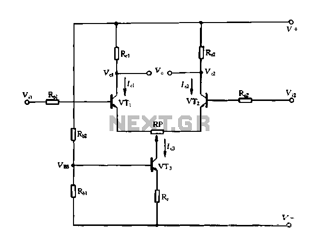
A differential amplifier with a constant current source is illustrated in Figure 1-27. As long as capacitor C3 is maintained at a constant value, capacitors C1 and C2 cannot be simultaneously increased or decreased, preventing voltage drift. The differential...
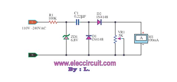
This meter displays the frequency of a power generator, which operates at a voltage range of 110V-240V and a frequency range of 10-100Hz. The output sine waves are converted to square waves. The described frequency meter is designed to accurately...
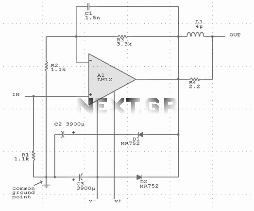
Output-clamp diodes are mandatory because loudspeakers are inductive loads. Output LR isolation is also used because audio amplifiers are usually expected to handle up to 2 mF load capacitance. Large, supply-bypass capacitors located close to the IC are used...
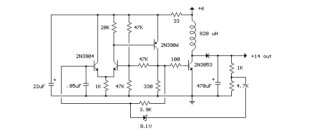
This compact switching power supply utilizes a Schmitt trigger oscillator to control a switching transistor, which provides current to a small inductor. When the transistor is activated, energy accumulates in the inductor, and this energy is subsequently released into...