
Current Limiting Power Supply
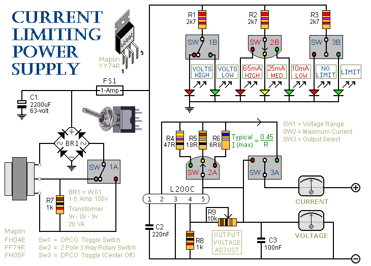
This circuit description pertains to a power supply unit equipped with adjustable current limiting features. The switch SW3 serves a dual function as both an on/off switch and a selector for the mode of operation, either with a current limit or without. This flexibility allows users to choose between a regulated output where current is restricted to a predetermined level and an unrestricted output where the load can draw as much current as required, potentially leading to overcurrent situations.
The second switch, SW2, is integral to setting the current limit, providing three distinct options determined by the resistors R4, R5, and R6. These resistors are configured to establish current limits of 10mA, 25mA, and 65mA, respectively. Each resistor can be replaced or adjusted to customize the current limits according to the specific requirements of the application. This feature allows for flexibility in the design of the circuit, accommodating various load conditions.
The operation of the circuit is safeguarded by a feedback mechanism that monitors the output current. If the load attempts to draw more current than the selected limit, the output voltage will decrease, thereby protecting the circuit and the connected load from damage due to excessive current. This voltage drop is indicative of the current limiting action and can be monitored using a voltmeter connected to the output. The voltmeter serves as a visual indicator, alerting the user when the load exceeds the permissible current threshold, thus ensuring safe operation of the circuit under varying load conditions.
Overall, this design highlights the importance of current limiting in power supply circuits, providing both safety and flexibility for various electronic applications.SW3 is the on/off switch. It also lets you choose between the output with the current limit and the one without. SW2 provides a selection of three different limits. You can increase or decrease this number if you wish. The limits are fixed by R4, R5 & R6. They are set at 10mA, 25mA & 65mA respectively; but you can choose whatever limits you like. If you try to draw a current above the limit you`ve selected, the output voltage will fall. Thus, the voltmeter indicates when the load on the output is excessive. 🔗 External reference
Related Circuits
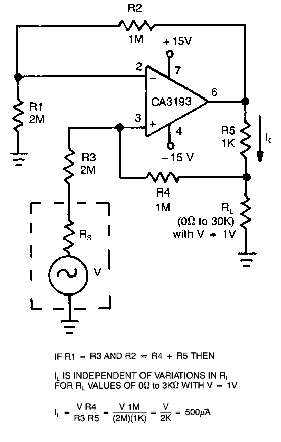
This circuit employs a CA3193 precision operational amplifier to provide a current that remains consistent regardless of variations in the load resistance (RL). By configuring the input resistance (RI) to be equal to resistance R3 and setting resistance R2...
Currently, a basic MOSFET amplifier or power amplifier is designed to deliver an output power of ±100 Watts RMS with an 8 Ohm load, or ±160 Watts RMS with a 4 Ohm load. The simplicity of this circuit results...
This application note describes the evaluation board for the AD7892-2, a 12-bit analog-to-digital (A/D) converter. The AD7892-2 is a high-speed, low-power device capable of 500 ksps sampling rate, operating from a single +5V supply. It features an on-chip track/hold...
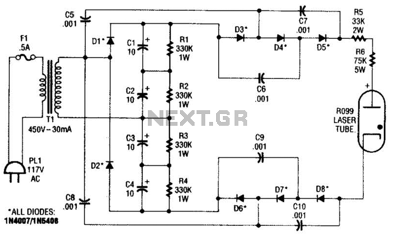
This supply generates an initial high voltage for ignition purposes. After ignition, the supply generates about 1300 to 1500 V. If a higher ignition voltage (than the 6000 V supplied) is necessary, more multiplier stages can be added to...
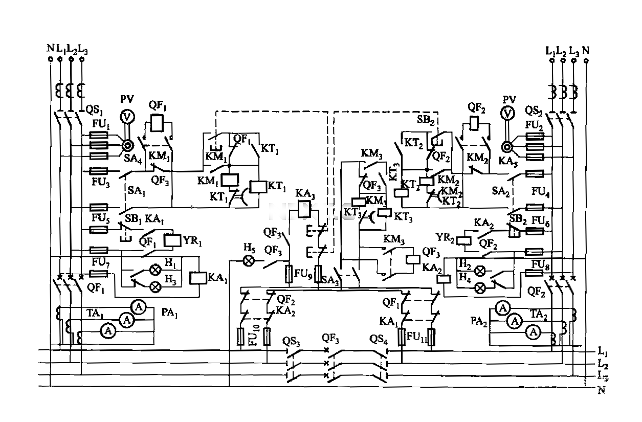
Dual power is provided for each complex, as the load is supplied through a two-way power system. In the event of a power outage, the contact switches transition from a closed position, allowing the power supply circuit to bear...
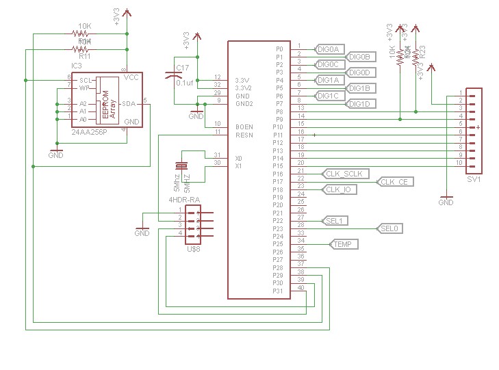
After constructing numerous Nixie Tube Clocks based on online designs, a personal design was developed. This clock utilizes IN-12 Nixie Tubes and an 8-core Propeller Microcontroller. Although the Propeller may be more powerful than necessary for this task, it...