
Current Loop
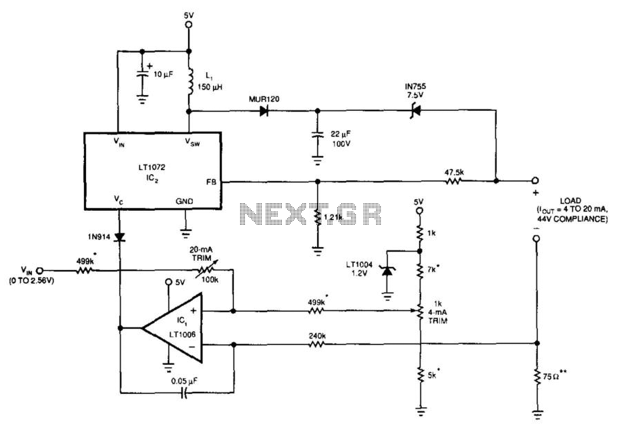
This circuit operates effectively within the specified parameters by utilizing a servo-controlled DC/DC converter that ensures stable compliance voltage. The design is optimized for driving current through resistive loads, making it suitable for applications requiring precise current regulation. The compliance voltage of up to 44 V allows the circuit to accommodate a wide range of load impedances, specifically up to 2200 ohms, while maintaining the desired current output of 4 to 20 mA.
The inclusion of short-circuit protection is a critical feature, safeguarding the circuit from potential damage due to overload conditions. The current source design inherently limits the output current, ensuring that the circuit remains within safe operating limits regardless of the load characteristics.
The interaction between the input voltage and the 4-mA trim network is essential for setting the positive input voltage of IC1. This configuration ensures that the output of IC1 effectively biases the Vc pin of the LT1072, allowing for proper regulation and operation of the switching regulator. The feedback mechanism involving the resistors connected to the fb pin is crucial for maintaining stability in the circuit. It prevents the output voltage from rising uncontrollably in scenarios where the load may become disconnected.
In normal operation, IC1 manages the regulation loop; however, the design anticipates conditions where feedback may be lost, such as an open load. In such cases, the FB pin's activation at 1.2 V triggers a local closure of the regulation loop, engaging the internal amplifier of IC2. This automatic transition from current regulation to voltage regulation is a sophisticated feature that enhances circuit reliability by preventing excessive output voltages that could lead to component failure or damage to connected loads. Overall, this circuit exemplifies effective design principles in electronic regulation, combining functionality with safety measures to ensure robust performance. This 5-V circuit utilizes a servo-controlled dc/dc converter to generate the compliance voltage necessary for loop- current requirements. This circuit will drive 4 to 20 mA into loads as high as 2 200 with 44 V of compliance. It is inherently short-circuit protected. A current source by definition limits current regardless of the load. The circuit"s input voltage and the 4-mA trim network determine ICl"s positive input voltage. ICl"s output biases the LT1072 switching regulator"s Vc pin. The resistors connected to the regulator"s feedback pin, fb, prevent the circuit output from running away in the event that the load opens up. Normally, IC1 controls the loop. However, if the load opens, IC1 receives no feedback. Under this condition, the FB pin becomes active when it equals 1.2 V and forces the loop to close locally around the regulator by activating IC2"s internal amplifier.
Thus, the circuit automatically changes from a current to a voltage regulator, thereby preventing excessive output voltages. 🔗 External reference
Related Circuits
Figure 1 shows the circuit. A major change from all of the designs from that era is the speaker coupling capacitor - 1000uF (for a -3dB of 20Hz and a 8 Ohm load) was the most common value. This is...
A filter removes the DC component of the rectified AC, which is then scaled to RMS. The output is linear from 40 Hz to 10 kHz or higher. The described circuit primarily consists of a filter designed to eliminate the...
The current loop interface circuit diagram of the AD694 multi-functional sensor signal conditioner is utilized as a digital-to-analog converter (DAC). This current loop interface enables the conversion of digital values into voltage and subsequently into current signals. The circuit...
The following are current regulator circuits that can be used to drive light emitting diodes. As always, take time to do some testing before attempting to use these circuits in actual applications. Current regulator circuits are essential for controlling the...
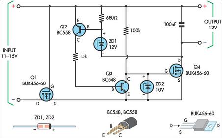
This circuit is designed to power a laptop computer using a solar power setup. The computer requires 12V at 3.3A. The circuit employs a linear regulator with a MOSFET (Q4) as the series pass device. A 100kΩ resistor provides...
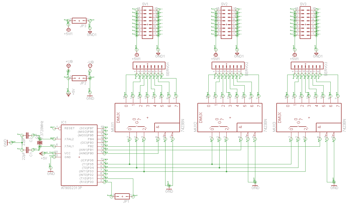
A serial servo controller is being developed to enhance knowledge of electronics and assembly language as part of a hexapod robot project. Initially, the ATTiny2313 microcontroller was utilized; however, it became evident that additional I/O channels were necessary. Consequently,...