
Current-to-voltage converter
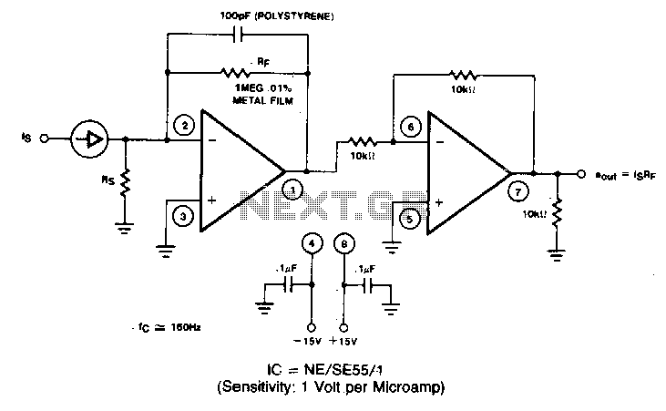
The described circuit primarily consists of a filter designed to eliminate the direct current (DC) component from a rectified alternating current (AC) signal. This is typically achieved using a combination of capacitors and resistors configured in a low-pass filter arrangement. The purpose of this filter is to allow the alternating current component of the signal to pass while blocking any DC offset, thereby ensuring that the output signal accurately represents the AC waveform without any DC bias.
After the filtering process, the signal is scaled to represent its root mean square (RMS) value, which is a crucial measurement in AC signal processing. The RMS scaling can be performed using an RMS-to-DC converter, which provides a stable output voltage proportional to the RMS value of the input AC signal. This conversion is essential for applications where accurate power calculations or signal analysis are required.
The circuit’s output is specified to be linear across a frequency range from 40 Hz to 10 kHz or higher. This linearity indicates that the filter and scaling circuitry can accurately reproduce the input signal characteristics within this frequency range, making the circuit suitable for audio applications, signal processing, and other electronic systems where fidelity of the AC signal is critical. The ability to maintain linearity over this range ensures minimal distortion and accurate representation of the original signal, which is vital for high-quality audio and precise measurements in various electronic applications.A filter removes the dc component of the rectified ac, which is then scaled to RMS The output is linear from 40 Hz to 10 kHz or higher. 🔗 External reference
Related Circuits
The BiMOS CA3140 operational amplifier offers excellent orientation capabilities for high bandwidth signal inputs and can swiftly adjust the energy output at its terminal CA33IO WINE. The CA3140 can also operate close to the negative supply rail. If the...
This 6V to 12V converter circuit is made with an IC from SGS with several additional components. The IC is a TDA2003 but it can be replaced with a TDA2002. The cost of building the 6 volts to 12...
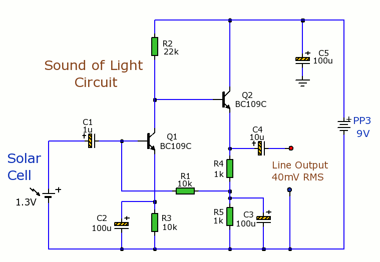
Solar Cells Light-Sound Converter. This is an experimental circuit that converts light into sound. The Solar Cells Light-Sound Converter is an innovative circuit designed to transduce light energy into acoustic signals. This experimental setup utilizes photovoltaic cells to capture ambient...
First circuit is for connecting VGA card to video projector or a monitor which accept VGA card frequencies and has RGB + Composite sync input. This circuit has been successfully used with Electrohome Projection Systems ECP 4100 data and...
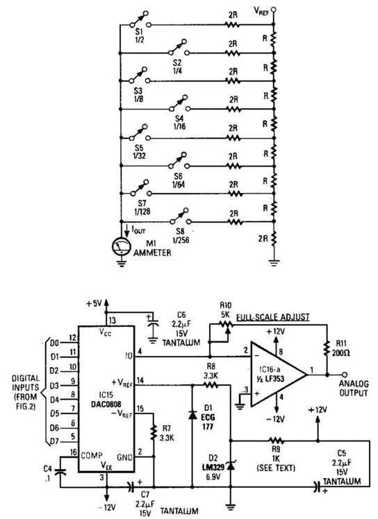
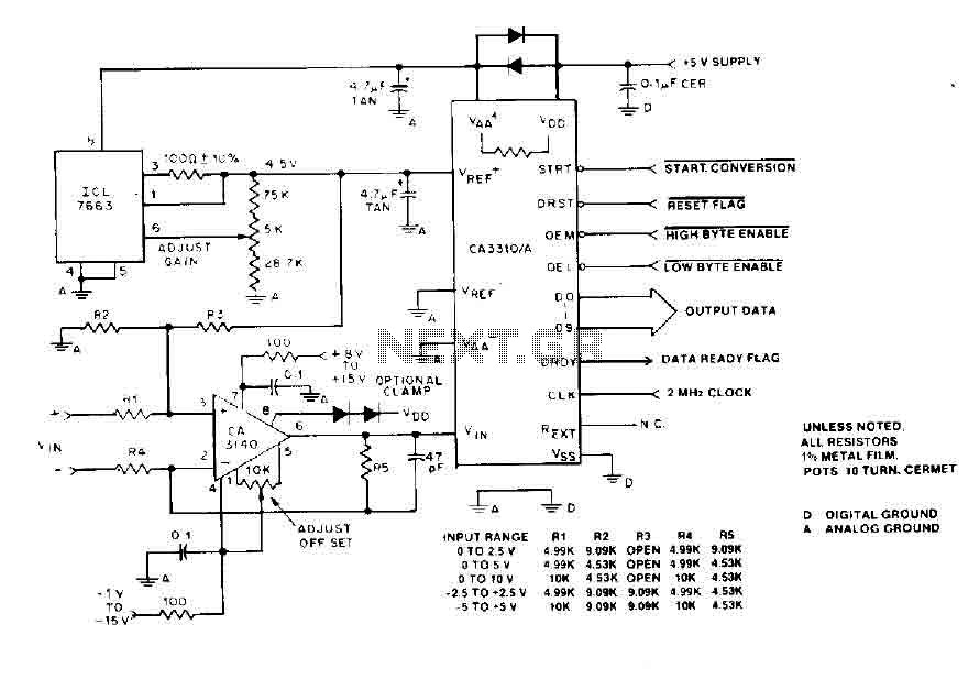
Figure A illustrates an R/2R resistor ladder. Each closed switch increases the current output. A basic channel A/D converter is depicted in Figure B. The voltage reference (D2) is shared among all channels, while the value of the dropping...
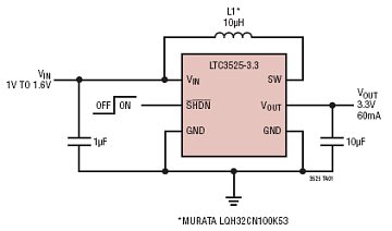
The LTC3525-3/LTC3525-3.3/LTC3525-5 are high-efficiency synchronous step-up DC/DC converters with output disconnect capability that can operate with an input voltage as low as 1V. These converters provide a compact and efficient alternative to charge pumps for single-cell or dual-cell alkaline...