
Current source not working in AD7792
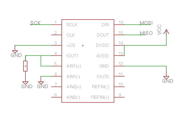
The circuit involves a serial interface that communicates with an integrated circuit (IC) capable of sourcing current through designated output pins, specifically IOUT1 and IOUT2. The configuration of the IO register with the value 0x03 indicates that both output pins are set to provide a current of 1mA. The presence of a 470-ohm resistor connected to IOUT1 is intended to allow for the measurement of the output voltage, which should theoretically be calculated using Ohm's Law (V = I × R). Therefore, with a current of 1mA flowing through a 470-ohm resistor, the expected voltage drop across the resistor should be 470 mV.
The observed voltage of only 33 mV suggests a significant discrepancy, indicating that the current sourcing capability of the circuit may be compromised. Potential causes for this issue could include incorrect configuration of the IO register, a malfunctioning current source within the IC, or issues related to the power supply or ground connections. The testing of two separate boards helps to rule out manufacturing defects, such as a faulty chip or poor soldering practices, reinforcing the need to investigate the internal circuitry of the IC or the associated components further.
To troubleshoot the issue, it may be beneficial to verify the supply voltage levels and ensure that the IC is receiving adequate power. Additionally, checking the integrity of the connections to the IOUT pins and confirming that the IO register is correctly programmed could provide insights into the problem. If the current sources remain non-functional, further analysis of the IC's specifications and operational limits may be necessary to determine if external factors are influencing its performance.The serial interface is working fine (Read the ID register correctly) but for some reason the on-chip current sources doesn`t seem to work. I have connected 470E resistor on IOUT1 and have configured the IO register (Value 0x03) so that 1mA is sourced on both IOUT1 & IOUT2.
I`m expecting to see 470 mV across the resistor, but I`m getting 33mV. I h ave tried making 2 of such boards to rule out possibility of bad chip or bad soldering, 🔗 External reference
Related Circuits
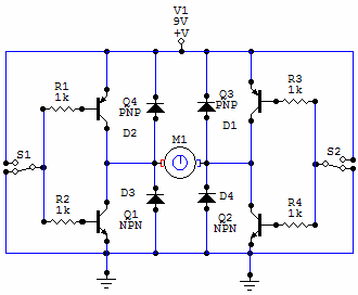
You have 4 transistors, wired as ON OFF switches. Two signal lines allow you to run the motor in one direction, when reversed, the motor runs in the other direction. It's very straightforward to use and build, but be...
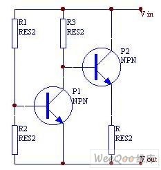
When a transistor junction operates in Zener breakdown as a noise source, the resulting noise signal exhibits asymmetry in amplitude. This issue can be addressed by employing two transistors as independent noise sources. One transistor is connected with a...
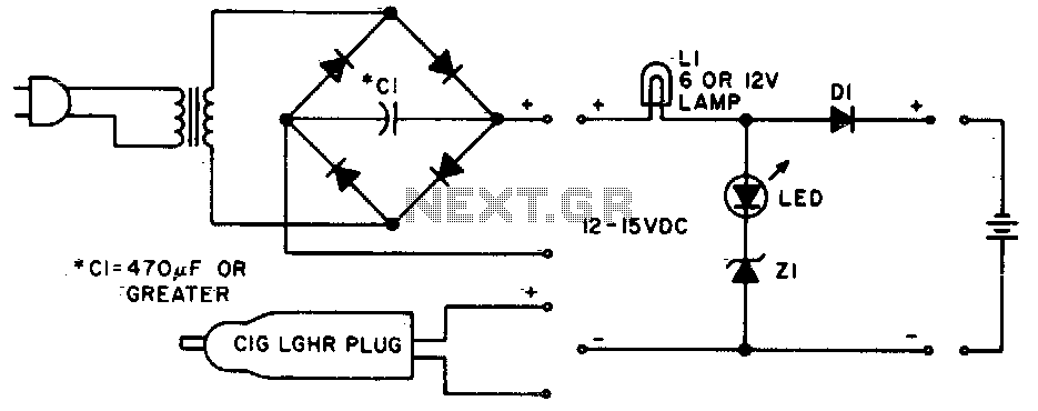
Lamp LI will glow brightly while the LED remains off when the battery is low and charging. Conversely, the LED will illuminate brightly, and the light bulb will be dim when the battery is nearly charged. Lamp LI should...
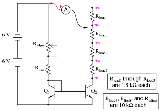
Two NPN transistors, specifically models 2N2222 or 2N3403, are recommended for this circuit. Larger "power" transistors may not behave similarly at low current levels. However, any pair of identical NPN transistors can be utilized to construct a current mirror....
When the current is below the specified threshold, the bias current supplied by resistor R1 causes transistor P3 to saturate and conduct. In this state, it is unable to regulate the current effectively. Conversely, when the current reaches or...
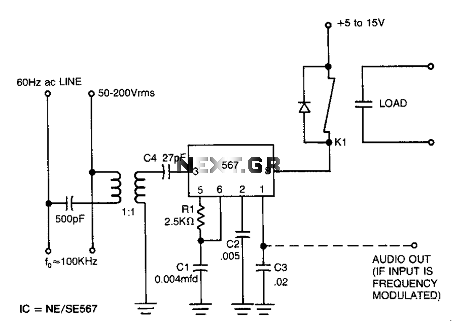
Carrier current remote control device or intercom circuit diagram as follows: The circuit diagram for a carrier current remote control device or intercom system typically involves the use of carrier current technology to transmit audio signals over existing electrical...