
curve tracer adaptor schematics

The circuit design integrates several critical components to ensure precise measurements and reliable operation. The dual trace oscilloscope allows for simultaneous observation of voltage and current, facilitating the analysis of circuit behavior under various conditions. The use of operational amplifiers IC2a and IC2b is pivotal in providing the necessary signal conditioning and isolation, which minimizes the impact of cable capacitance on the measurements. The relay system enhances the versatility of the testing setup by enabling quick switching between different probes, thereby allowing for comparative analysis without the need for extensive manual reconnections.
Moreover, the adjustable sine wave input is crucial for testing a wide range of devices, from low-voltage sensitive components to those requiring higher voltage levels for functional verification. The specification of using shielded coaxial cables and low-resistance probe leads emphasizes the importance of maintaining signal integrity and reducing noise interference, which are critical factors in accurate electronic measurements.
In summary, this oscilloscope-based testing unit serves as a comprehensive tool for evaluating the performance of various electronic components, providing essential insights into their operational characteristics while ensuring measurement accuracy through careful design considerations.This unit employs a dual trace oscilloscope with X-Y function as a display to test and demonstrate the action of circuits and components such as transistors, diodes, zener diodes, and terminated and unterminated transformers. A low frequency sinewave (ie 10Hz - 1kHz) is applied to op amp IC2a via potentiometer VR1 to set the "X" and "Y" levels for
the X-Y display on the scope. The output of IC2a is applied to the X input via R4 and IC2b and also to Probe 1 via the contacts of relay 1. IC2b provides a low impedance drive for the X input and also isolates the X input cable capacitance from probe 1.
The current flowing into the probes develops a voltage across R4 which is processed by IC2d and applied to the CRO Y input to represent current. The scope display thus represents an X-Y graph where voltage across a circuit under test is displayed on the X axis (horizontal) and the current though it displayed on the Y axis (vertical).
With a calibrated scope this equates to 1mA/V. IC1 and a relay are included to enable two probes to be used and comparisons made between a known good device and a faulty one. The relay should be a low capacitance reed type. By using the scope`s X and Y gain controls, the sinewave applied to the device under test should be adjustable from a few millivolts up to 24V peak-peak to get a very useable display.
Thus, the unit can be used on voltage sensitive devices and at the other end of the scale apply enough voltage to check the operation of, say, a 10V zener diode. Note that all devices should be tested in the unpowered condition. If used for in-circuit tests, the effects of circuit components will need to be taken into account. Shielded coax leads should be used for the X and Y inputs and the probe leads should have zero resistance.
Normal scope probes should not be used as these usually have significant built-in resistance which will interfere with measurements. 🔗 External reference
Related Circuits
The circuit automatically powers down a computer after Windows has been shut down, preventing users from forgetting to turn off their machines. Upon shutting down Windows, a click occurs after one second, disconnecting the PC from the mains supply....
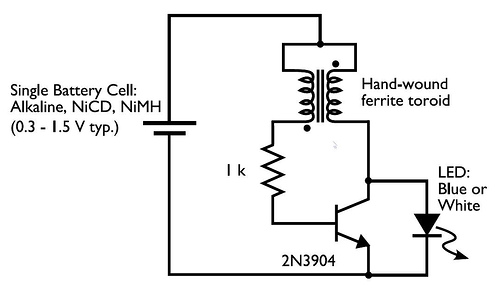
In the circuit diagram for the Joule Thief, the common point of the toroid is the connection at the top of the hand-wound ferrite toroid, located in the upper right of the diagram. This connection leads to the positive...
Utilize the program to customize your experience with the woven tules of roses on a single Adobe 3 Mac card. The system's reading portion remains idle while the controller operates, as illustrated in Figure 1. This setup includes the...
A simple test circuit to fault find audio and radio equipment. Can be used to inject a square wave signal, rich in harmonics, or used with headphones as an audio tracer. A single pole double throw switch is used...
Approximately 20 years ago, it was common to encounter small key-holders that emitted an intermittent beep for a few seconds after the owner whistled. These devices utilized a specialized integrated circuit (IC) and were not suitable for home construction....
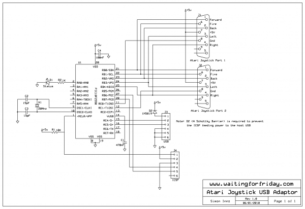
This project implements a composite USB device that supports two USB 2.0 full-speed gameport HID interfaces. The physical joystick ports are wired according to the Atari standard, allowing the connection of most Commodore 64 and Amiga joysticks, as well...