
low volt led flasher schematics
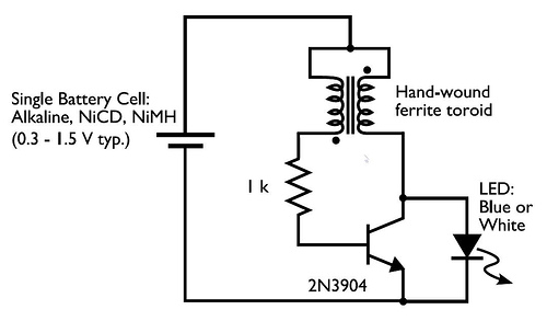
The Joule Thief is a simple and efficient circuit designed to extract energy from low-voltage sources, such as single-cell batteries, and boost it to a higher voltage sufficient to power an LED. The circuit primarily consists of a toroidal inductor, a transistor (commonly the 2N3904), a resistor, and an LED.
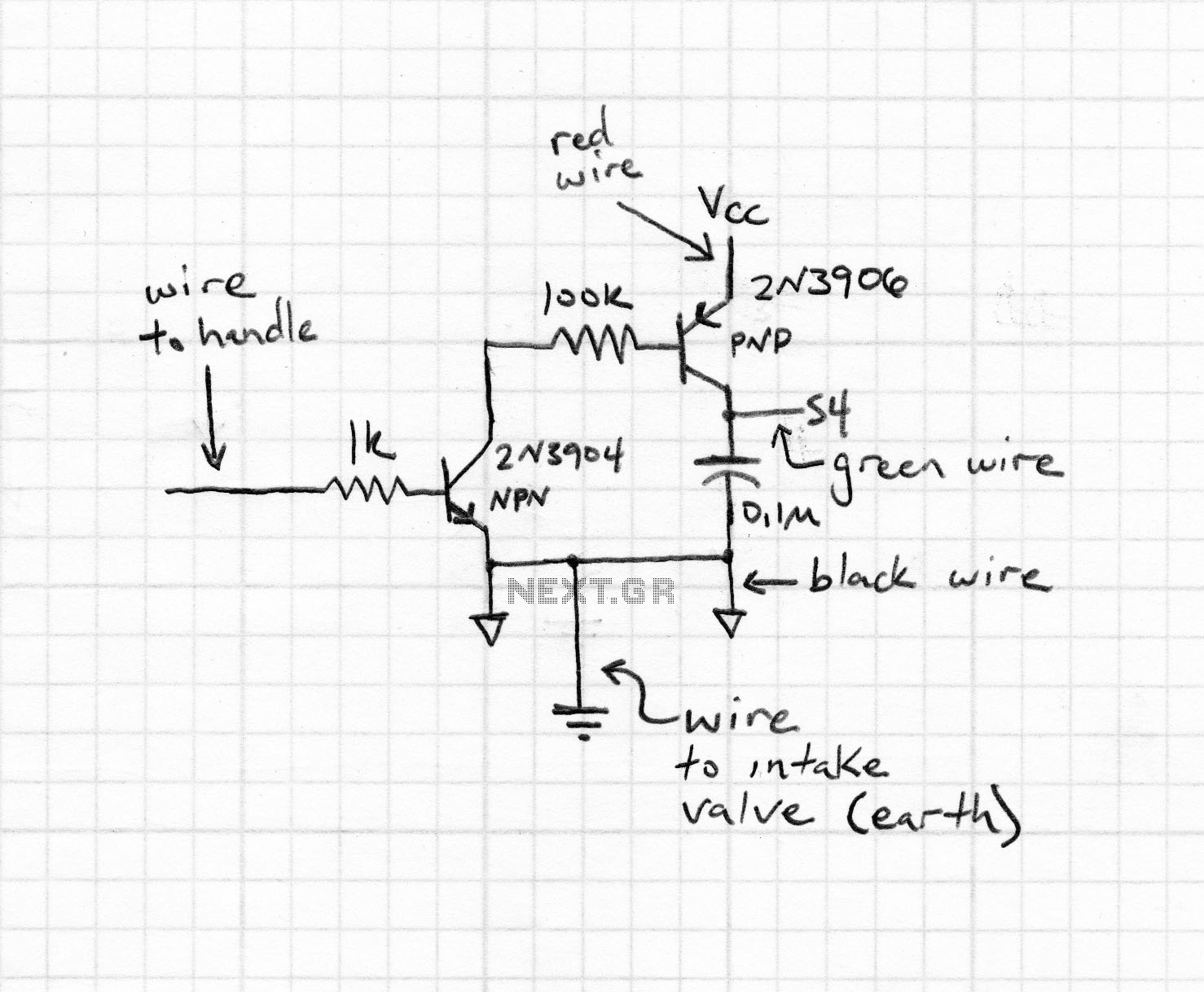
In this circuit, the ferrite toroid serves as an inductor, which is crucial for energy storage and transfer. The winding of the toroid creates a magnetic field when current flows through it. The connection at the top of the toroid to the positive terminal of the battery establishes the power supply. The two additional leads from the toroid connect to the resistor and the transistor. The resistor is typically used to limit the base current flowing into the transistor, ensuring it operates within safe limits.
The transistor, specifically the 2N3904, is a bipolar junction transistor (BJT) that functions as a switch in this configuration. The emitter, represented by the arrow in the schematic, is connected to ground, while the collector is linked to the LED. The base, which controls the transistor's operation, receives the signal from the toroid through the resistor. When the circuit is powered, current flows from the battery through the toroid, inducing a magnetic field that causes the transistor to switch on and off rapidly. This oscillation allows energy to be transferred to the LED, producing light.
The LED in the circuit is polarized, meaning it has a specific orientation. The flat side and shorter lead indicate the cathode, which must be connected to the lower potential side of the circuit. The correct connection of the LED is essential for its operation, as reversing the polarity may damage the component.
Overall, the Joule Thief circuit exemplifies the principles of inductive energy transfer and transistor switching, making it an effective solution for utilizing low-voltage power sources efficiently.In the circuit diagram for the Joule Thief, the common point of the toroid is the connection at the top of the hand-wound ferrite toroid, in the upper right of the diagram. This goes to the positive end of the battery. The other two wires from the toroid go to the resistor and to the intersection of the transistor with the LED.
One other detail th at you may need to know is the symbol and pinout of the 2N3904 transistor. In the symbol, the part with the arrow is the emitter , the collector is the end above it, that also connects to the LED, and the base is the wire leading off to the left, between the collector and emitter. (Also remember that the end of the LED with the flat side and short lead is the end that has the flat bar in the diagram.
) 🔗 External reference
Related Circuits
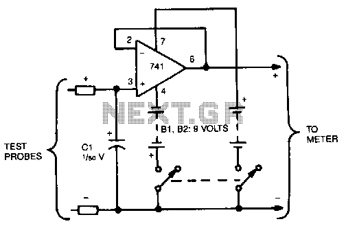
This circuit reads and stores voltages, thereby freezing the meter reading even after the probes are removed. The operational amplifier (op-amp) is configured as a unity-gain voltage follower, with capacitor C1 located at the input to store the voltage....
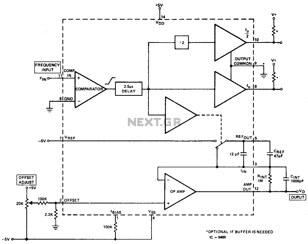
The converter produces an output voltage that is linearly proportional to the input frequency waveform. Each zero crossing at the comparator's input results in a specific amount of charge being dispensed into the op-amp's summing junction. This charge subsequently...
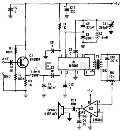
Using an NE602 heterodyne detector and U1 as an RF amplifier, this receiver tunes the middle portion of the low-frequency spectrum from 150 to 250 kHz. U2 is a loudspeaker amplifier. The described circuit employs an NE602 integrated circuit...
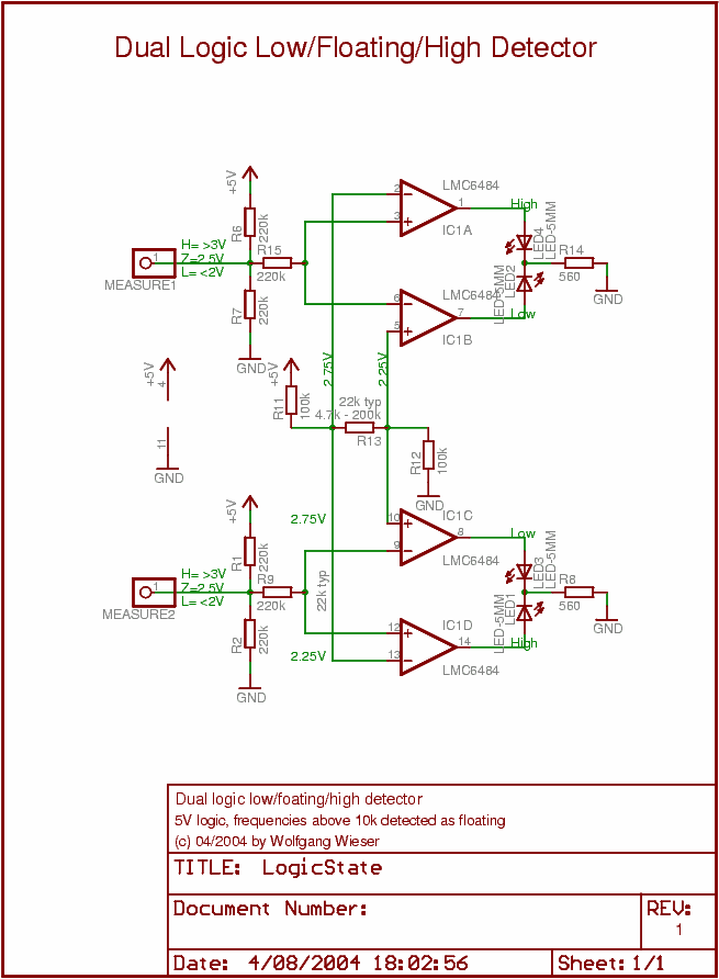
This circuit is a dual low/floating/high logic state detector that allows observation of the logic state of a digital signal pin. Each detector features two LEDs (typically one red and one green) to indicate the state: the red LED...
This is the fifth iteration of a robot named Cruddy version 2. It functions as a line-following robot and features an improved circuit design, originally conceived by the designer. Notably, this project does not utilize a microcontroller; instead, it...
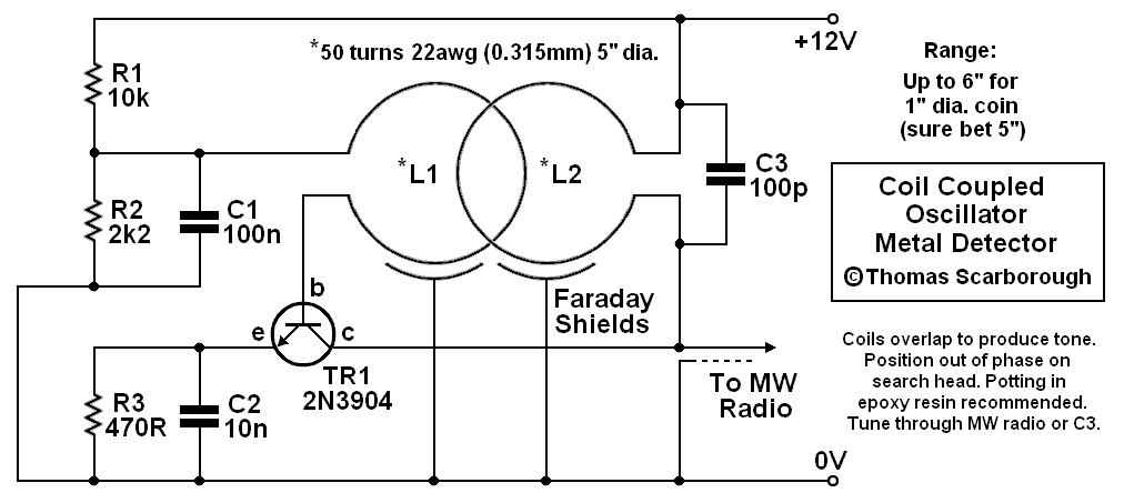
The metal detector presented may represent a new category in its field. After some exposure, it has been recognized as such by those familiar with it. This device is based on a standard transformer coupled oscillator (TCO), which is...
Warning: include(partials/cookie-banner.php): Failed to open stream: Permission denied in /var/www/html/nextgr/view-circuit.php on line 713
Warning: include(): Failed opening 'partials/cookie-banner.php' for inclusion (include_path='.:/usr/share/php') in /var/www/html/nextgr/view-circuit.php on line 713