
Signal Tracer

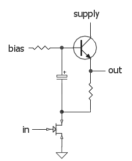
The circuit operates in two primary modes: injection and tracing. In tracing mode, the circuit functions as an audio tracer, allowing for the detection of audio signals in various equipment. The single pole double throw (SPDT) switch enables seamless transition between modes. In tracing mode, the earpiece is connected to the collector of the final transistor, which is configured as an emitter follower. This configuration ensures high input impedance and low output impedance, making it ideal for interfacing with the sensitive audio signals from the equipment under test.
The circuit utilizes two transistors, both configured as emitter followers, which provide significant voltage gain while maintaining a linear response. The use of a 1n capacitor at the probe end serves as a DC blocking element, preventing any DC component from interfering with the audio signal being traced. The capacitive coupling between the two stages further enhances the circuit's ability to handle a wide range of frequencies without distortion.
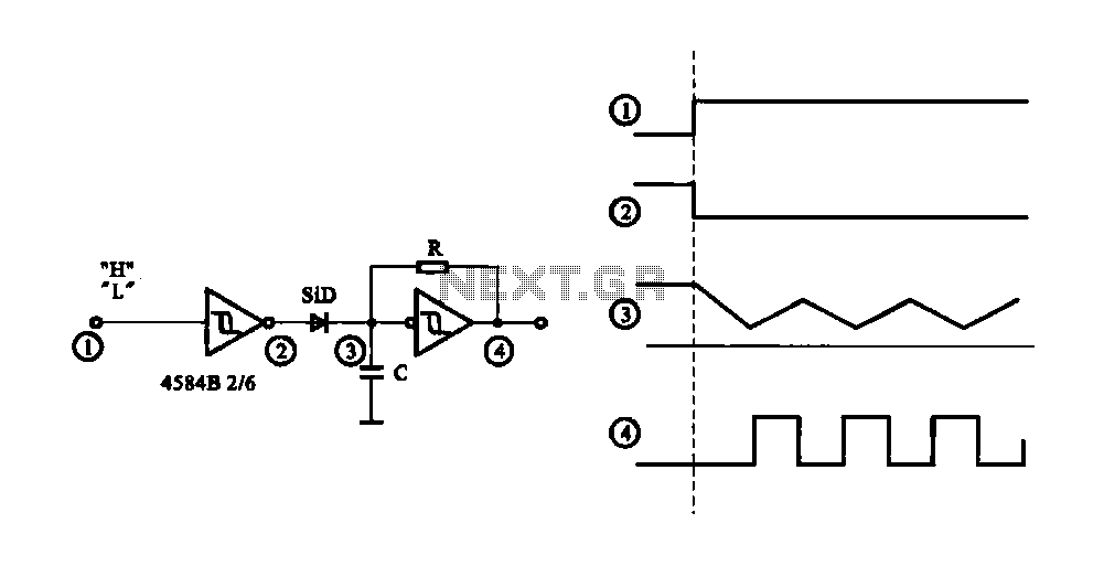
In injection mode, when the SPDT switch is toggled to the opposite position, the circuit transforms into an astable multivibrator. This configuration generates a square wave signal rich in harmonics, useful for testing the frequency response of audio devices and AM radio receivers. The output frequency can be adjusted by modifying the resistor and capacitor values in the feedback network of the transistors, allowing for a range of frequencies from audio up to several hundred kilohertz. This versatility makes the circuit an invaluable tool for electronics technicians and hobbyists in diagnosing and troubleshooting audio and radio equipment.A simple test circuit to fault find audio and radio equipment. Can be used to inject a square wave signal, rich in harmonics, or used with headphones as an audio tracer. A single pole double throw sitch is used to switch between inject and trace modes. The diagram is drawn in trace mode, the earpiece being connected to the collector of the last transistor.
Both transistors are wired as emitter followers, providing high gain. DC blocking is provided by the 1n capacitor at the probe end, and the two stages are capacitively coupled. When the switch is thrown the opposite way (to the blue dot) both transistors are wired as an astable square wave generator. This provides enough harmonics from audio up to several hundred kilohertz and is useful for testing AM radio Receivers.
🔗 External reference
Related Circuits
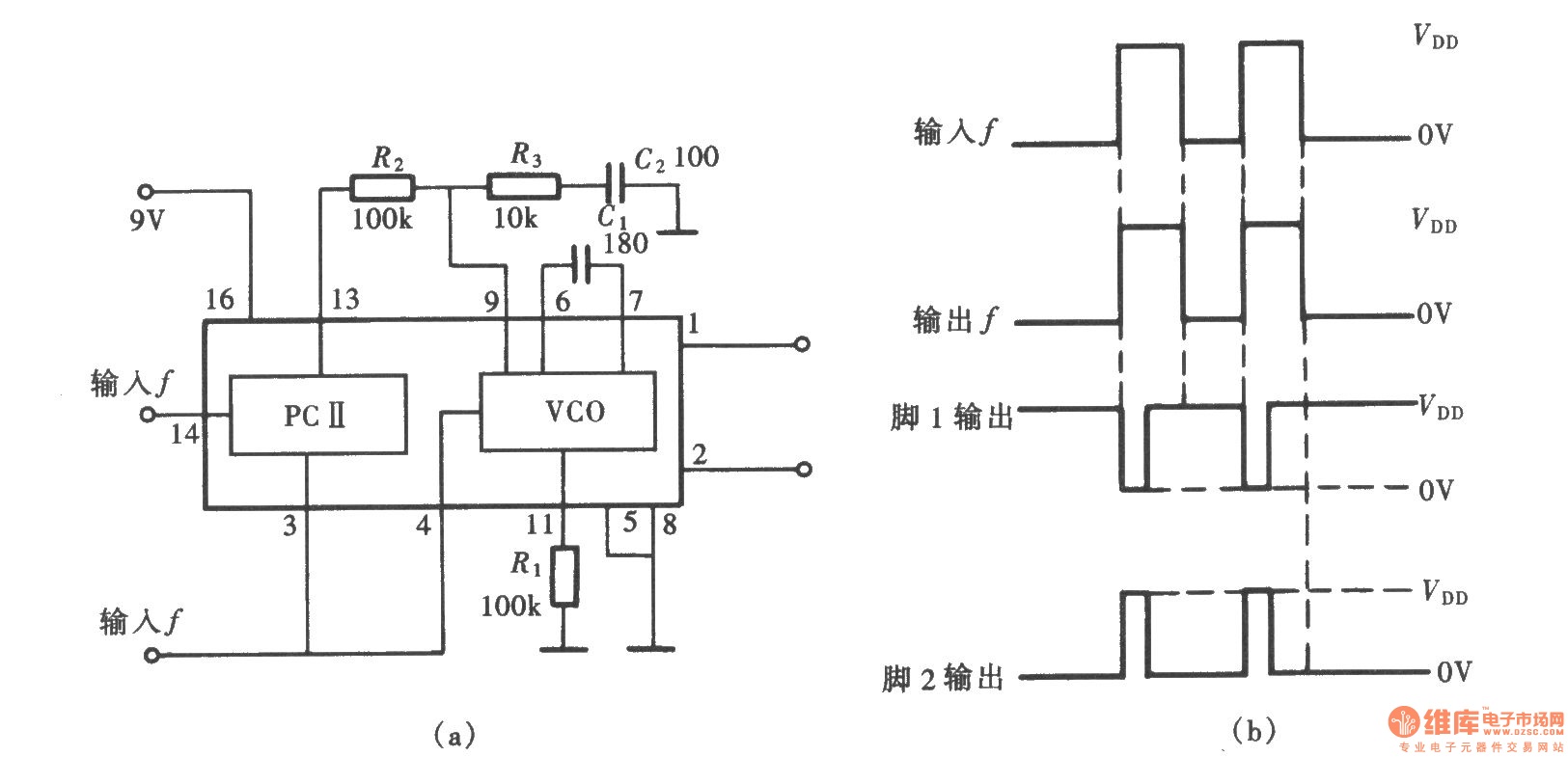
A frequency signal tracking circuit is implemented using a phase-locked loop (PLL) configuration, which is a fundamental application of the CD4046 integrated circuit. The circuit, illustrated in the accompanying chart, utilizes the CD4046 to form a PLL that effectively...
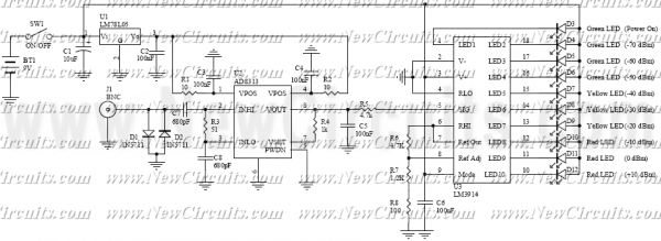
RF Signal Strength Meter circuits are popular RF measurement devices. This circuit is one of the simplest but very useful circuits that satisfies your desired accuracy. The heart of measurement is high accuracy but easy to use Logarithmic Detector...
The small 8-pin PIC12C508 is pre-programmed to generate our 38KHz carrier frequency by simply pulsing I/O-pin GP1. The PIC will generate either 38KHz or 40KHz, depending on the state of GP3 when power is first applied. If you connect...
This simple circuit generates narrow pulses at about 700-800Hz frequency. The pulses, containing harmonics up to the MHz region, can be injected into audio or radio-frequency stages of amplifiers, receivers and the like for testing purposes. A high-pitched tone...
The circuit generates a controlled pulse signal. When a high pulse signal is applied to the input terminal O (start), the output pulse signal is activated. Conversely, when a low signal is received at the input terminal O (stop),...
The audio source will be a line-level audio signal ranging from -2V to +2V AC, which will be passed through a 220µF coupling capacitor followed by a two-pole low-pass filter (RC). The signal will be processed by an Analog-to-Digital...