
cut off low circuit diagram
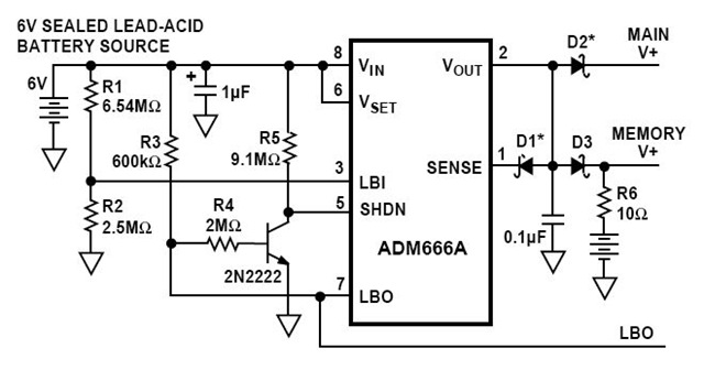
The solid-state charge detector circuit is designed to sense minute electric fields and provide a visual indication of their presence through an LED. The core components of the circuit include a 6-volt battery, which serves as the power supply, ensuring that the circuit operates efficiently. The light-emitting diode (LED) acts as an output indicator, illuminating when a detectable electric field is present.
The field-effect IC, specifically the ADM666A, plays a critical role in the circuit's operation. This integrated circuit is known for its high sensitivity and low power consumption, making it ideal for detecting weak electric fields. The IC operates by amplifying the small voltage changes caused by the electric fields, enabling the LED to light up even when the detected signal is significantly low.
To construct the circuit, the 6-volt battery is connected to the power input of the ADM666A, ensuring that the IC receives the necessary voltage for operation. The output pin of the ADM666A is connected to the anode of the LED, while the cathode of the LED is connected to ground. A current-limiting resistor is typically included in series with the LED to prevent excessive current flow, which could damage the LED.
In summary, this solid-state charge detector circuit effectively utilizes a combination of a 6-volt battery, an LED, and the ADM666A IC to detect weak electric fields and provide a visual output, making it a valuable tool for applications requiring sensitivity to low-level electric signals.This is a circuit diagram for a solid state charge detector. It can detect very weak electric fields. The circuit has three components: a 6-volt battery, a light-emitting diode (LED), and a field-effect IC ADM666A 🔗 External reference
Related Circuits
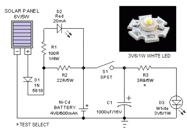
This portable solar lantern circuit utilizes a 6 volt/5 watt solar panel, which is widely available. With this photovoltaic panel, an economical, simple, yet efficient and truly portable solar lantern unit can be constructed. The next essential component required...
The crystal-controlled SoftRock receivers developed by Tony Parks (KB9YIG) have played a significant role in introducing many individuals to Software Defined Radio (SDR). For those who prefer not to be limited to a single frequency, the SoftRock Ensemble receivers...

This circuit is designed as a countdown timer utilizing a countdown calculation. It employs the 555 integrated circuit (IC) as the primary control element. The 555 IC functions as a counter and a transistor switch to activate a relay...
Radio Circuit Diagram Manual PDF Download. The radio circuit diagram manual provides a comprehensive guide for understanding and constructing radio circuits. It includes various circuit schematics, components specifications, and operational principles essential for both beginners and experienced engineers in the...
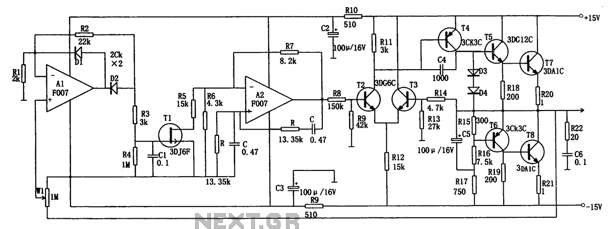
The low-frequency signal generating circuit demonstrates excellent performance characterized by stable operation, high output power, and minimal waveform distortion. It serves as an ideal source for low-frequency measurement signals. The circuit includes an operational amplifier (A) with a feedback...
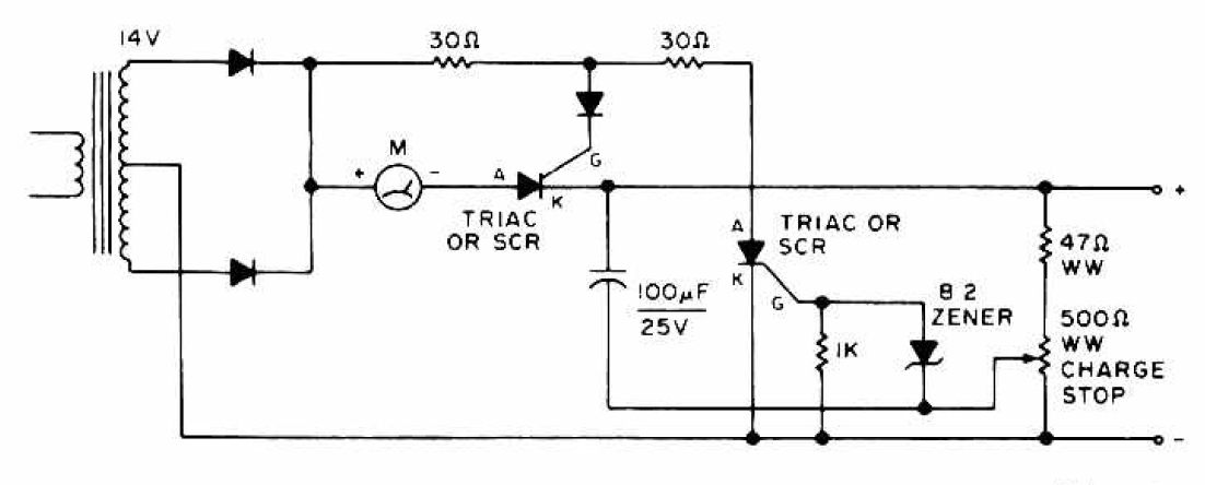
The charging circuit features adjustable voltage output settings, allowing for regulation of the charging voltage supplied to the battery. The use of a potentiometer facilitates precise voltage management, with adjustments possible down to the millivolt range. Refer to the...
Warning: include(partials/cookie-banner.php): Failed to open stream: Permission denied in /var/www/html/nextgr/view-circuit.php on line 713
Warning: include(): Failed opening 'partials/cookie-banner.php' for inclusion (include_path='.:/usr/share/php') in /var/www/html/nextgr/view-circuit.php on line 713