
portable solar lantern circuit uses 6

This portable solar lantern circuit is designed to harness solar energy efficiently, making it an ideal solution for outdoor lighting applications. The 6V/5W solar panel captures sunlight and converts it into electrical energy, generating about 9V DC under optimal conditions. This energy is used to charge a 4.8V Ni-Cd battery pack, which stores the energy for later use.
The charging process is indicated by the red LED (D2), which illuminates when the battery is charging. Resistor R1 is connected in series with D2 to limit the current flowing through the LED, ensuring it operates within safe limits. Resistor R2 plays a crucial role in regulating the charging current to the battery pack, maintaining it at approximately 150mA to prevent overcharging and extending the life of the battery.
During sunlight exposure of 4-5 hours, the solar panel is capable of delivering a total charge of 600-750 mAh to the battery pack, depending on the intensity of sunlight. This stored energy can then be utilized to power the high-power white LED (D3) when the power switch (S1) is turned on. Resistor R3 is used to control the current flowing through D3, ensuring it operates at the desired brightness without exceeding its rated specifications.
Capacitor C1 functions as a buffer, providing stability to the circuit by smoothing out any fluctuations in the voltage supply from the battery. This helps to maintain consistent LED performance and enhances the overall reliability of the solar lantern system. The combination of these components results in a compact, efficient, and environmentally friendly lighting solution suitable for various applications, including camping, emergency lighting, and outdoor events.This portable solar lantern circuit uses 6 volt/5 watt solar panels are now widely available. With the help of such a photo-voltaic panel we can construct an economical, simple but efficient and truly portable solar lantern unit. Next important component required is a high power (1watt) white LED module. When solar panel is well exposed to sunligh t, about 9 volt dc available from the panel can be used to recharge a 4. 8 volt /600 mAh rated Ni-Cd batterypack. Here red LED (D2) functions as a charging process indicator with the help of resistor R1. Resistor R2 regulates the charging current flow to near 150mA. Assuming a 4-5 hour sunlit day, the solar panel (150mA current set by the charge controller resistor R2) will pump about 600 750 mAh into the battery pack. When power switch S1 is turned on, dc supply from the Ni-Cd battery pack is extended to the white LED (D3).
Resistor R3 determines the LED current. Capacitor C1 works as a buffer. 🔗 External reference
Related Circuits
The circuit illustrates the use of three frequencies to produce a graphic equalizer that will be used for acoustic signals. The equalizer can be either passive or active. The graphic equalizer circuit operates by dividing the audio frequency spectrum into...
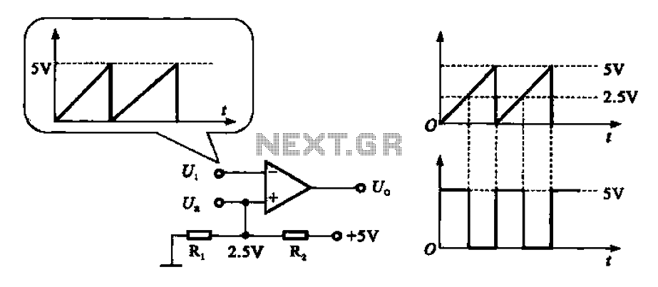
The addition and subtraction functions of an operational amplifier are facilitated through an external feedback network, which places the integrated operational amplifier in a deep state of negative feedback. In this linear region, the relationship between input and output...

Figure 1-30 illustrates an example of an output capacitor-less (OCL) power amplifier circuit, which can be analyzed as follows: In this circuit, transistors VTi and VTz form a single-ended input and a differential input single-ended output amplifier configuration. The...
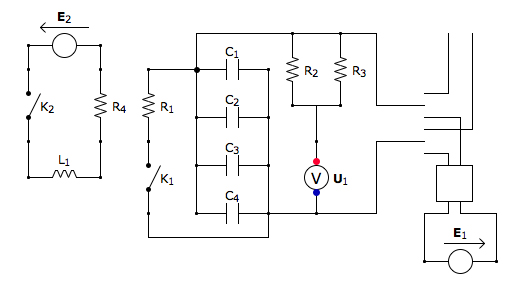
This is the discharging circuit. The red lines indicate the flow of energy from the capacitors to the terminals when the switch is in the upward position. The circuit is complete due to the connection of the terminals by...
This circuit diagram represents a microphone preamplifier, specifically designed to prioritize voice signals over other audio inputs. In its basic configuration, the circuit includes a microphone unit and a change-over switch that connects to an amplifier. When the push-to-talk...
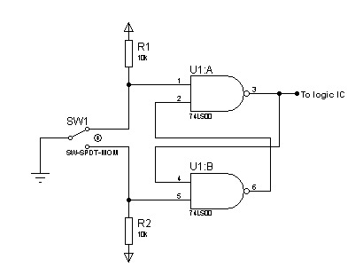
In most digital electronics projects that utilize various types of switches, switch bounces are frequently encountered. These are additional glitches that occur following the actual operation of the switch. These small pulses can disrupt the proper functioning of the...