
microcontroller Digital bargraph display driver circuit
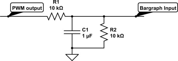
To implement a digital-to-analog conversion suitable for driving the LM3914 bar graph display using the available digital outputs from the PIC16F84A, a resistor ladder network can be employed. This network will convert the digital signals into a corresponding voltage level that the LM3914 can interpret as an analog input.
The circuit can be designed using the following components:
1. **Resistor Ladder**: A series of resistors can be connected between the digital output pins of the MCU and ground. The values of the resistors will determine the voltage levels corresponding to different digital combinations of the output pins. For instance, using two digital pins can create four distinct voltage levels (00, 01, 10, 11) which can be translated into four different positions on the bar graph.
2. **LM3914 Configuration**: The LM3914 can be configured in bar mode to light up the appropriate number of segments based on the voltage input it receives from the resistor ladder. The reference voltage for the LM3914 can be set using a potentiometer connected to the V+ pin, allowing for adjustment of the maximum value displayed on the bar graph.
3. **Microcontroller Programming**: The PIC16F84A can be programmed to change the state of its output pins according to the desired progress level. By manipulating the two data pins, the MCU can create the necessary digital combinations that will result in the appropriate voltage levels at the output of the resistor ladder.
4. **Schematic Representation**: The schematic will consist of the PIC16F84A connected to two resistors forming a ladder network, which in turn connects to the input of the LM3914. The output of the LM3914 will drive the bar graph display directly.
This approach allows for effective use of the limited pins available on the microcontroller while ensuring that the bar graph display functions correctly without the need for additional costly components such as an IO expander. The resistor ladder configuration is a cost-effective solution for digital-to-analog conversion in this application.For a project I need to display a progress bar of the activity performed by my MCU. For this purpose I am going to use a bargraph display, but the problem is that bargraph display driver driver IC LM3914 uses analog input where as MCU produces a digital output. How can I display a value on bargraph using digital input instead of analog The bargra ph should display values from lower to higher and higher to lower. Schematics will be highly appreciated. I only have two data pins available on uC (PIC16F84a) to drive a Bargraph display, and IO expander will increase the cost of system. I tried IC 4017 for the purpose, but it provides only one ON pin at a time. 🔗 External reference
Related Circuits
This 300W RF power amplifier for an FM transmitter utilizes 2 x TP9383 transistors. It operates within the 88 - 108 MHz frequency band. The 300W RF power amplifier is designed specifically for FM transmission applications, providing high power output...
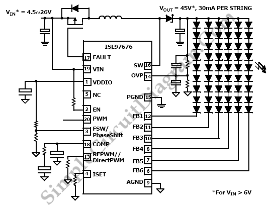
The ISL97676 can be utilized as an LED driver capable of managing six channels of LED current for TFT displays. This driver supports the operation of up to 78 LEDs with a voltage range of 4.5V to 26V, or...
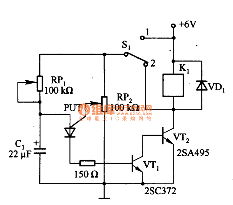
Figure 1 consists of a Programmable Unijunction Transistor (PUT) and an automatic interval timer circuit. In this circuit, the PUT serves as the oscillator. The switch S1 is used to toggle between interval timing and automatic timing modes. When...
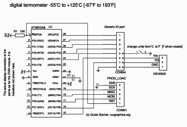
The Mini 3-digit display, also known as the "DVM-module" (digital voltmeter module), can be easily tuned and modified due to firmware control. Key advantages of this module include an internal reference voltage of 2.56V in the ATmega8 microcontroller. By...
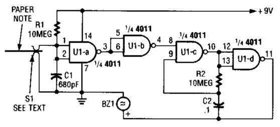
This device prevents paper notes and memos from being overlooked. A paper note placed between two fingers made of a conducting material (metal or conductive plastic) breaks the circuit, allowing pair 1 of Ul-a to go high. The goal...
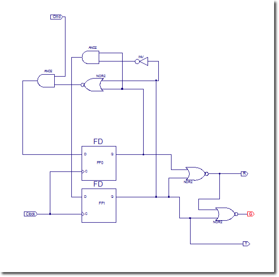
In this lab, flip-flops will be utilized. Xilinx provides a comprehensive library of sequential circuits, which is recommended for circuit searches: Xilinx Reference Library. The objective of this lab is to implement a sequential circuit that controls three LEDs:...
Warning: include(partials/cookie-banner.php): Failed to open stream: Permission denied in /var/www/html/nextgr/view-circuit.php on line 713
Warning: include(): Failed opening 'partials/cookie-banner.php' for inclusion (include_path='.:/usr/share/php') in /var/www/html/nextgr/view-circuit.php on line 713