
circuit transistor tester
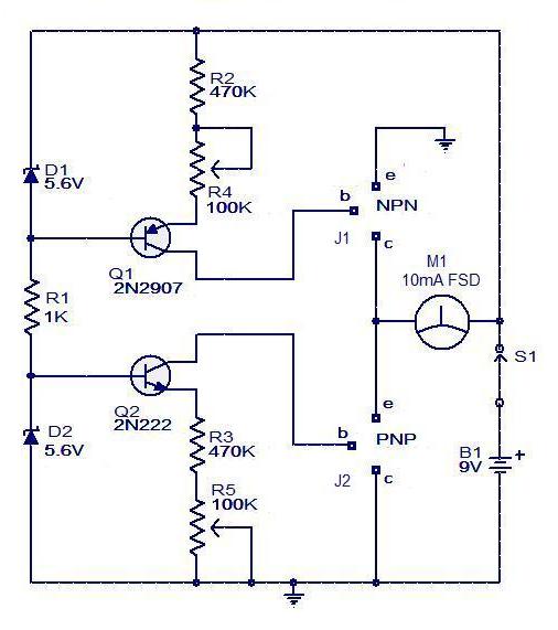
The transistor tester circuit is designed to facilitate the evaluation of both NPN and PNP transistors, providing a user-friendly interface for identifying transistor functionality. Upon connecting the transistor to terminals J1 and J2, the circuit automatically determines the type of transistor based on the biasing configuration. The inclusion of the ammeter allows for real-time monitoring of the collector or emitter current, providing valuable feedback on the transistor's operational state.
The bias control circuit is critical for accurately measuring the transistor's characteristics. For NPN transistors, when the base is biased through R4, the circuit allows current to flow from the collector to the emitter, enabling the ammeter to display the corresponding collector current. In contrast, the PNP transistor configuration requires the bias to be applied through Q2, R5, and D2, allowing for the measurement of the emitter current.
The choice of a 9V power source is optimal for ensuring sufficient voltage levels for testing various transistor types while maintaining safety and ease of use. The supporting components, including resistors and diodes, are selected to provide stability and protection against potential overcurrent situations during testing.
Overall, this transistor tester circuit serves as an essential tool for electronics engineers and hobbyists alike, allowing for quick and effective testing of transistor functionality and characteristics. It simplifies the process of identifying faulty components and aids in the design and troubleshooting of electronic circuits.Circuit transistor tester is a fairly simple circuit tester. Transistor tester circuit shown below can be used to measure and know the pins and determine the condition of the transistor. In addition this circuit transistor tester can also find out what kind of transistors are measured. Transistor tester circuit is built with 2 transistor, an amper e meter, and some supporting components. Transitor Circuit tester can be operated using a DC voltage source from a 9V battery or power supply. J1 and J2 on the circuit transistor tester is a terminal for the transistor to be on the test. Transistor tester circuit in detail can be seen in the following figure. Bias control transistor serves to regulate the transistor base bias in the test. To test the NPN transistor base bias controlled by R4 Q1 and D1. Then to test the PNP transistor base bias is controlled by Q2 R5 and D2. Transistor base bias control circuit is basically a set amount of voltage and current to the transistor base is tested.
Meter in the circuit transistor tester is an ampere meter to display functioning at the transistor collector current Ic and the current NPN transistor PNP emitter on the on the test. 🔗 External reference
Related Circuits
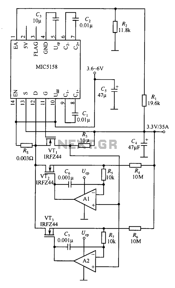
The MIC5158 is designed to manage tasks by controlling multiple external N-channel MOSFETs in parallel, which enables high current or high power output for a linear regulator circuit. This is illustrated in the accompanying figure. The operational amplifier circuit...
A 2 µF capacitor is charged to approximately 340 volts, and the discharge is controlled by a silicon-controlled rectifier (SCR). A Schmitt trigger oscillator (74C14) and a MOSFET (IRF510) are utilized to drive the low-voltage side of a small...

This game can be played individually or with friends. The circuit consists of a timer IC, two decade counters, and a display driver paired with a 7-segment display. The objective of the game is straightforward: the player who reaches...
This circuit turns off an amplifier or any other device when it remains idle for 15 minutes. It is powered by the amplifier's tape output. The described circuit functions as an automatic power management system, designed to enhance energy efficiency...
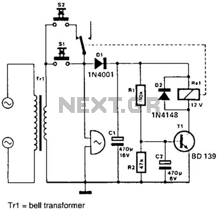
It is often desirable for a single doorbell to be operated by two buttons, for instance, one at the front door and the other at the back door. The additional button, S2 in series with the break contact of...

The composite pipe circuit limits the bulb cold current of the circuit. When the input signal is weak, a composite pipe circuit protection circuit is utilized, as illustrated in Figure 1. The composite pipe circuit functions as a protective mechanism...
Warning: include(partials/cookie-banner.php): Failed to open stream: Permission denied in /var/www/html/nextgr/view-circuit.php on line 713
Warning: include(): Failed opening 'partials/cookie-banner.php' for inclusion (include_path='.:/usr/share/php') in /var/www/html/nextgr/view-circuit.php on line 713