
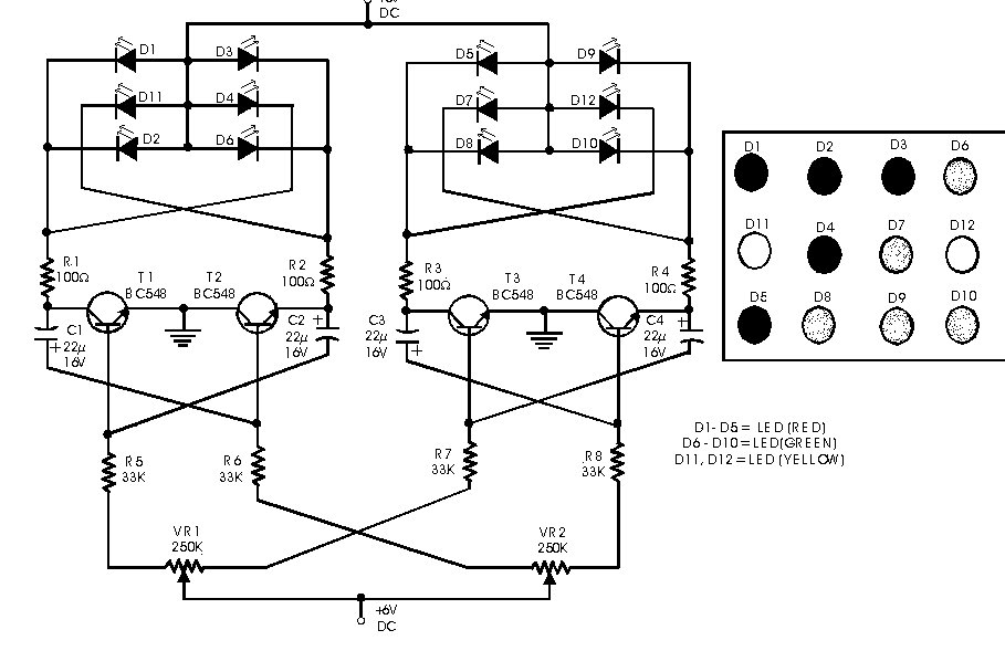
Dancing LEDs

The circuit operates by first capturing audio signals through a microphone, which is then amplified by IC1A, enhancing the signal to a level suitable for further processing. IC1B serves as a peak detector, ensuring that the output corresponds to the peaks of the audio input, thus maintaining synchronization with the audio rhythm. The output from IC1B is fed into IC2, which is configured as a ring decade counter. This component sequentially activates the LEDs based on the timing of the audio peaks, creating a visual representation of the sound.
The additional circuit for driving LED strips incorporates a constant current source that stabilizes the current flowing through the LEDs, preventing variations that could lead to uneven brightness or damage. The switching transistor (Q3) is essential for controlling the individual strips, allowing for flexibility in the number of LEDs connected in series. The design facilitates easy modifications; for instance, adjusting the number of LEDs per strip can be accomplished by changing the connections to pin #15 of IC2, allowing for configurations that suit different applications or aesthetic preferences.
Power supply considerations are also addressed in the design. While the circuit is optimized for a 9V battery, it can accommodate higher voltages, such as 12V or 15V, which increases the maximum number of LEDs that can be used per strip. This adaptability allows for greater versatility in installation scenarios, whether powered by batteries or a wall adapter. The overall design emphasizes efficiency, ease of use, and the ability to create visually appealing light displays that respond dynamically to audio inputs.The basic circuit illuminates up to ten LEDs in sequence, following the rhythm of music or speech picked-up by a small microphone. The expanded version can drive up to ten strips, formed by up to five LEDs each, at 9V supply. IC1A amplifies about 100 times the audio signal picked-up by the microphone and drives IC1B acting as peak-voltage detector
. Its output peaks are synchronous with the peaks of the input signal and clock IC2, a ring decade counter capable of driving up to ten LEDs in sequence. An additional circuit allows the driving of up to ten strips, made up by five LEDs each (max. ), at 9V supply. It is formed by a 10mA constant current source (Q1 & Q2) common to all LED strips and by a switching transistor (Q3), driving a strip obtained from 2 to 5 series-connected LEDs.
Therefore one transistor and its Base resistor are required to drive each of the strips used. Adopting the additional circuit, only one item for R10, R11, Q1 and Q2 is required to drive up to ten LED strips. On the contrary, one item of R9 and Q3 is necessary to drive each of the strips you decided to use. For example: if you decided to use 5 LEDs, pin #15 of IC2 must be connected to pin #1; if you decided to use 8 LEDs, pin #15 of IC2 must be connected to pin #9 etc.
Whishing to use a wall-plug adapter instead of a 9V battery, you can supply the circuit at 12V, allowing the use of up to 6 LEDs per strip, or at 15V, allowing the use of up to 7 LEDs per strip. 🔗 External reference
Related Circuits

The Spartan-6 board features 16 LEDs connected to FPGA I/O pins, as detailed in the table below. The cathode of each LED is connected to ground through a 330-ohm resistor. To illuminate a specific LED, the corresponding FPGA control...
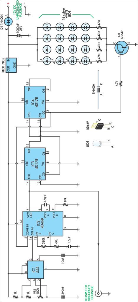
This stroboscope circuit employs 16 high-brightness white LEDs housed in a torch and provides a signal output to a frequency counter for rev counter display. The circuit utilizes IC1, a 555 astable multivibrator, which generates a signal for IC2,...
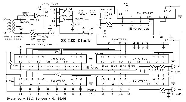
This is a programmable clock timer circuit that uses individual LEDs to indicate hours and minutes. 12 LEDs can be arranged in a circle to represent the 12 hours of a clock face and an additional 12 LEDs can...

In this project, eight LEDs are connected to PORT B of a PIC microcontroller. A push-button switch is also connected to bit 0 of PORT A using a pull-up resistor. When the switch is pressed, the LEDs scroll to...
Here is a simple circuit which can be used for decoration purposes or as an indicator. Flashing or dancing speed of LEDs can be adjusted and various dancing patterns of lights can be formed. The circuit consists of two...
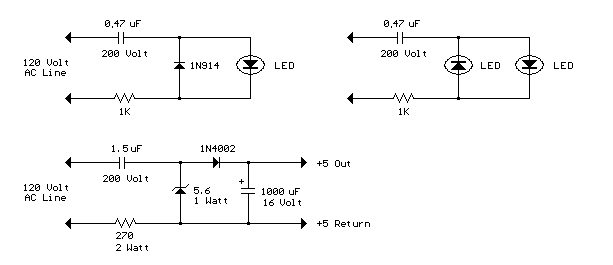
The circuit below illustrates powering a LED (or two) from the 120 volt AC line using a capacitor to drop the voltage and a small resistor to limit the inrush current. Since the capacitor must pass current in both...