
Power LEDs from Mains
The described circuit utilizes a capacitive dropper method to power one or two LEDs directly from a 120V AC supply. The primary components include a non-polarized capacitor, a resistor, and a diode (or an alternative LED). The capacitor is essential for reducing the AC voltage to a level suitable for the LED, while the resistor limits the initial inrush current when the circuit is powered on.
The choice of a 1K ohm resistor rated for half a watt is crucial, as it effectively limits the worst-case inrush current to approximately 150 mA. Upon charging, the inrush current quickly drops to less than 30 mA within a millisecond, indicating a safe operational range for the LED. The capacitor, rated at 0.47 µF, exhibits a reactance of 5600 ohms at a frequency of 60 Hz, allowing for an average LED current of around 10 mA, which is suitable for standard LED operation.
For enhanced functionality, a small diode is placed in parallel with the LED to facilitate current flow during the negative half-cycle of the AC waveform. This diode also protects the LED from reverse voltage, which could otherwise lead to damage. Alternatively, a second LED can be used in reverse polarity to achieve similar results, or a tri-color LED can be integrated to display an orange color when powered by the alternating current.
Furthermore, the circuit can be expanded to include a zener diode configuration for applications requiring a regulated low voltage output. The zener diode acts as a voltage regulator, allowing for a stable output voltage of approximately 5 volts while supplying over 30 mA of current with minimal ripple (around 300 mV). This setup is particularly beneficial for powering low-voltage devices directly from the AC line, though caution is advised due to the inherent risks associated with direct AC connections.
Overall, this circuit design provides an efficient and compact solution for powering LEDs and low-voltage applications from a standard AC supply, while ensuring adequate protection and regulation.The circuit below illustrates powering a LED (or two) from the 120 volt AC line using a capacitor to drop the voltage and a small resistor to limit the inrush current. Since the capacitor must pass current in both directions, a small diode is connected in parallel with the LED to provide a path for the negative half cycle and also to limit the reverse voltage across the LED.
A second LED with the polarity reversed may be subsituted for the diode, or a tri-color LED could be used which would appear orange with alternating current. The circuit is fairly efficient and draws only about a half watt from the line. The resistor value (1K / half watt) was chosen to limit the worst case inrush current to about 150 mA which will drop to less than 30 mA in a millisecond as the capacitor charges. This appears to be a safe value, I have switched the circuit on and off many times without damage to the LED.
The 0.47 uF capacitor has a reactance of 5600 ohms at 60 cycles so the LED current is about 20 mA half wave, or 10 mA average. A larger capacitor will increase the current and a smaller one will reduce it. The capacitor must be a non-polarized type with a voltage rating of 200 volts or more. The lower circuit is an example of obtaining a low regulated voltage from the AC line. The zener diode serves as a regulator and also provides a path for the negative half cycle current when it conducts in the forward direction.
In this example the output voltage is about 5 volts and will provide over 30 milliamps with about 300 millivolts of ripple. Use caution when operating any circuits connected directly to the AC line. 🔗 External reference
Related Circuits
The losses in a bridge rectifier can become significant when low voltages are being rectified. The voltage drop across the bridge is approximately 1.5 V, which represents about 25% of an input voltage of 6V. The loss can be...

The circuit of the transmitter is depicted in Figure 1, showcasing its simplicity. The initial stage is the oscillator, which is tuned using a variable capacitor. To select an unused frequency, adjust C3 carefully until background noise ceases (the...
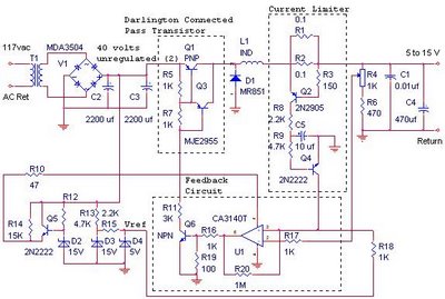
The switching power supply provides 12 volts at a maximum of 10 amps, utilizing a discrete transistor regulator with an operational amplifier acting as a comparator in the feedback circuit. The schematic does not depict the front panel power-on...
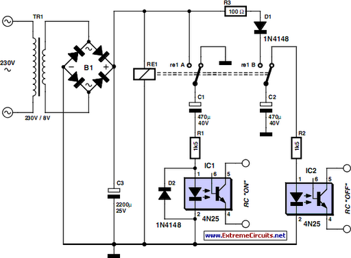
The request for assistance came from an elderly lady in a retirement home. In her room, the light switch by the door and the pull cord above the bed control the ceiling light fitting. However, she prefers to operate...
More: A comprehensive electronic schematic involves the representation of electrical components and their interconnections in a circuit. Each component is typically represented by standardized symbols, and the connections between them are depicted using lines. The schematic provides essential information...
If 40 watts RMS from 20Hz to 30KHz +/-1.5 dB is appealing, this experiment may be of interest. A significant issue with public address equipment is the use of audio output transformers that lack sufficient iron to manage lower...
Warning: include(partials/cookie-banner.php): Failed to open stream: Permission denied in /var/www/html/nextgr/view-circuit.php on line 713
Warning: include(): Failed opening 'partials/cookie-banner.php' for inclusion (include_path='.:/usr/share/php') in /var/www/html/nextgr/view-circuit.php on line 713