
Right-left scrolling LEDs

The circuit design features a PIC16F627 microcontroller, which serves as the central control unit for the project. The microcontroller operates at a frequency of 4 MHz, providing sufficient speed for processing the input from the push-button switch and controlling the LED outputs. The use of PORT B allows for direct control of eight separate LEDs, each connected through a 330-ohm resistor, which limits the current to prevent damage to the LEDs.
The push-button switch connected to PORT A (specifically bit 0) enables user interaction, allowing the direction of the LED scrolling to be modified. The inclusion of a pull-up resistor ensures that the pin is held high when the switch is not engaged, providing a clear logic state for the microcontroller to read.
The program is structured to continuously monitor the state of the switch, leveraging a simple loop to determine the current scrolling direction. The use of a variable, Cnt, manages the LED positions and is updated in each iteration of the loop. The PEEK instruction reads the state of the switch, allowing the program to respond to user input effectively.
The configuration of TRISA and TRISB registers is critical, as it defines the operational roles of the respective pins. By setting TRISA to 1, the microcontroller designates bit 0 as an input, while clearing TRISB allows for output functionality across all associated pins. The CMCON register's configuration to 7 ensures that PORTA operates in digital mode, avoiding any interference from analog functions.
Overall, this project showcases the integration of a microcontroller with basic input and output components, demonstrating fundamental principles of digital electronics and microcontroller programming. The implementation of delays between LED state changes introduces a visually appealing effect, enhancing the user experience. The continuous loop structure ensures ongoing responsiveness to user interactions, making the circuit dynamic and engaging.In this project, 8 LEDs are connected to PORT B of a PIC microcontroller. Also a push-button switch is connected to bit 0 of PORT A using a pull-up resistor. When the switch is pressed the LEDs scroll to the right. The circuit diagram of the project is shown in Figure 1. The circuit in this project additionally a switch is connected to bit 0 of PO RTA to control the direction of scrolling. A PIC16F627 model PIC micro controller is used and the micro controller is operated from its 4 MHz internal clock. The LEDs are connected to 8 pins of PORT B using 330_ current-limiting resistors. An external reset button is connected to MCLR input of the microcontroller. The flow diagram of the project is shown in Figure 2. At the beginning of the program the I/O direction is specified. A byte variable called Cnt is used as the loop variable. The program consists of an indefinite loop and at the beginning of the loop the switch is tested. If the switch is logic 1 (i. e. switch is not pressed) then the scrolling is to the left and if the switch is pressed the switch is at logic 0 and scrolling is to the right.
A 250 ms delay is used between each output. The software for PicBasic language is given in Figure 3. At the beginning of the program PORTA, PORTB, TRISA, TRISB, and CMCON register addresses are defined. TRISA is set to 1 so that bit 0 of PORTA is configured as an input port. Similarly, TRISB is cleared to 0 so that all bits of PORTB are configured as outputs. Push-button switch is connected to bit 0 of PORTA (RA0). Normally this pin is pulled high to logic 1 by using a resistor. When the switch is pressed the pin goes down to logic 0. PORTA pins on the PIC16F627 microcontroller have dual functions and they can either be used as analog comparator inputs, or as digital I/O ports.
CMCON register is used to control the function of these pins. Setting CMCON to 7 configures PORTA pins as digital I/O ports. Inside the LOOP, the value of Cnt is sent to PORTB and the PEEK instruction is used to read the switch setting. Bit0 refers to bit 0 of variable B0 which is where the switch is connected. When the switch is pressed the program jumps to label PRESSED where the LEDs are scrolled right. When the switch is not pressed the LEDs are scrolled left. This loop is repeated forever with 250 ms delay between each output. Set port directions 🔗 External reference
Related Circuits

A circuit is needed to drive three or more LEDs at a current of 200-350mA each, with the capability to randomly flash or strobe them at a frequency of 5-20Hz. The input power should be low-voltage DC, with a...
A voltage supply ranging from 6 V to 15 V is required when using a single LED per module. An increase in the number of LEDs necessitates a corresponding increase in the voltage supply, with additional LEDs connected in...
The circuit is a 0-60 second timer using timer 555 and two 4017 for LED driving. The described circuit employs a 555 timer IC configured in monostable mode to create a timing interval ranging from 0 to 60 seconds. The...
This circuit operates two LED strips in pulsing mode, where one LED strip transitions from an off state to gradually lighting up, then dimming, while the other LED strip performs the opposite action. Each strip can consist of 2...
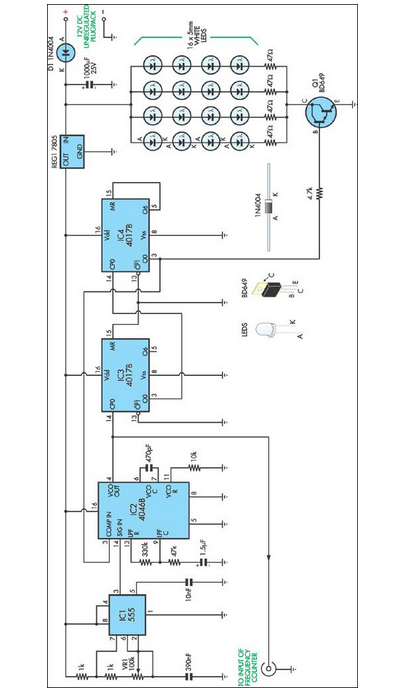
This stroboscope circuit utilizes 16 high-brightness white LEDs housed within a torch structure. It also offers a signal output to a frequency counter to indicate revolutions per minute (RPM). The stroboscope circuit is designed to provide visual indication of rotating...
A circuit was constructed based on an LED beating heart frame instructable, but it is not functioning as expected. There is also mention of a built LED sequencer. The LED beating heart circuit typically involves a microcontroller, such as an...