interfacing leds with spartan 6 fpga

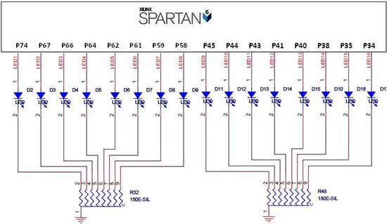
The Spartan-6 board features 16 LEDs connected to FPGA I/O pins, as detailed in the table below. The cathode of each LED is connected to ground through a 330-ohm resistor. To illuminate a specific LED, the corresponding FPGA control signal must be set to High.
The Spartan-6 FPGA board is designed to facilitate various digital applications, and it includes a configuration for driving multiple LEDs. Each LED is connected to a dedicated I/O pin on the FPGA, allowing for individual control of each light. The 330-ohm resistors serve to limit the current flowing through the LEDs, preventing damage and ensuring proper operation.
The circuit operates on a simple principle where setting the control signal associated with an LED to a High state activates the LED, causing it to light up. This is accomplished by providing the necessary forward voltage to the LED through the I/O pin, while the resistor ensures that the current remains within safe limits.
The arrangement of the LEDs and resistors can be represented in a schematic diagram, where each LED is symbolized alongside its corresponding resistor. The cathode of each LED is connected to ground, while the anode connects to the FPGA I/O pin through the resistor. This setup is commonly used in educational and prototyping environments to demonstrate digital output control, allowing users to visualize the effects of logic signals.
In practical applications, such a configuration can be expanded to include multiplexing techniques or more complex control logic, enabling the board to manage multiple LEDs in various patterns or sequences. This flexibility makes the Spartan-6 board a valuable tool for engineers and developers working on digital system designs.The Spartan-6 board has 16 LEDs Connected with FPGA I/O pins (details tabulated below). The cathode of each LED connects to ground via a 330 © resistor. To light an individual LED, drive the associated FPGA control signal to High. 🔗 External reference


