
Dark and Light Activated Relay circuit diagram
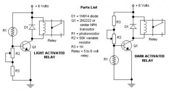
The circuit described involves a potentiometer that functions as a variable resistor, allowing for the adjustment of the trigger level in the circuit. This adjustment is crucial for fine-tuning the operation of the relay, ensuring that it activates at the desired threshold. The choice of diode is essential for reliable circuit performance; while the 1N914 is adequate for low-power applications, it is recommended to utilize a 1N4001 or a more robust diode to handle higher currents and reverse voltage spikes, thus ensuring the longevity and reliability of the circuit.
The 2N2222 transistor, known for its versatility in switching applications, can be replaced with several compatible alternatives such as NTE123A, ECG123A, and PN100. These substitutes provide similar characteristics in terms of current gain and switching speed, making them suitable for use in this circuit.
When designing the schematic, it is important to ensure that the connections between the potentiometer, diode, and transistor are clearly outlined. The potentiometer should be connected in such a way that it adjusts the voltage at the base of the transistor, which controls the relay operation. The diode should be placed in parallel with the relay coil to prevent back EMF from damaging the transistor when the relay is de-energized. Proper orientation of the diode is critical, with the anode connected to the ground side of the relay coil and the cathode connected to the supply voltage.
In summary, the circuit design must incorporate a potentiometer for trigger adjustment, a suitable diode for protection, and a reliable transistor for switching, ensuring that all components are compatible and correctly configured for optimal performance.The potensiometer adjust the trigger on` level. The diode in the circuit diagram shows to be 1N914. This is ok if you have a light-duty relay, also the 1N914 is a signal diode so actually does not qualify. Use a 1N4001 (or better) instead. A couple of substitutes for the 2N2222 transistor are: NTE123A, ECG123A, PN100, etc. We aim to transmit more information by carrying articles. Please send us an E-mail to wanghuali@hqew. net within 15 days if we are involved in the problems of article content, copyright or other problems. We will delete it soon. 🔗 External reference
Related Circuits
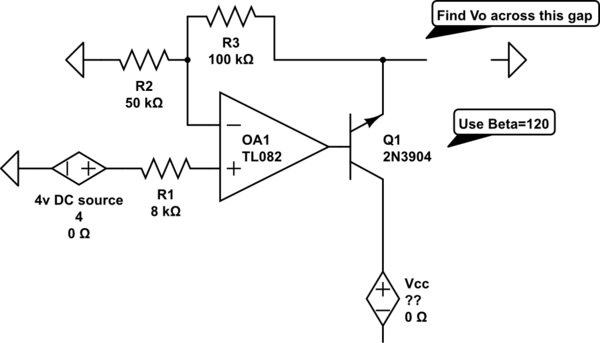
The voltage measured at 12V after the emitter is perplexing, especially when the output from the op-amp is +15V, suggesting a 3V drop across the transistor. This raises questions about the expected gain of 2, which would imply an...

This circuit can control the on/off cycle of a light using a CDS photocell and turn it off after a preset period. The light can only be activated when the CDS cell is in darkness, and it remains on...
A high-quality and straightforward intercom circuit utilizing only three transistors. By pressing switch S2, the circuit generates ringing signals. To create a two-way intercom, two identical circuits can be constructed and combined as illustrated in diagram 2. The circuit's...
To create a versatile and generic microcontroller board, the information provided thus far is sufficient. It covers the essential components needed to achieve this. The design of a microcontroller board requires careful consideration of various factors to ensure versatility and...

Input voltages can range from 8 V to 30 V. The load range for the 5 V output is from 0.05 A to 5 A, while the load range for the 3.3 V output is from 0.1 A to...
A CD4017 is configured as a senary counter, with an input clock frequency of 300 Hz. Diodes VD1 to VD9 and resistors R1 to R3 form three three-input OR gates, which can each receive two 50 Hz three-phase wave...
Warning: include(partials/cookie-banner.php): Failed to open stream: Permission denied in /var/www/html/nextgr/view-circuit.php on line 713
Warning: include(): Failed opening 'partials/cookie-banner.php' for inclusion (include_path='.:/usr/share/php') in /var/www/html/nextgr/view-circuit.php on line 713