
op amp Find Vo in an op-amp transistor circuit

The circuit in question appears to be a non-inverting operational amplifier configuration with negative feedback. In such a setup, the gain is defined by the resistor values connected to the feedback loop. The resistors R3 and R2 play a critical role in determining the overall gain of the circuit. The formula for gain in a non-inverting configuration is given by:
\[ \text{Gain} = 1 + \frac{R3}{R2} \]
In this case, R3 is 100 ohms and R2 is 50 ohms, leading to a calculated gain of 2. This means that for a given input voltage, the output should ideally be double the input. However, the observed output voltage of 12V indicates that the circuit is operating under specific conditions that necessitate further examination.
The confusion arises primarily from the feedback mechanism that is inherent to the operational amplifier. Negative feedback is employed to stabilize the gain and ensure that the output voltage does not exceed certain limits, which in this case seems to be capped at 12V. This feedback works by comparing the voltages at the inverting and non-inverting inputs of the op-amp. The op-amp will adjust its output to ensure that these two inputs are equal, thereby maintaining the desired operation of the circuit.
The mention of a variable power supply connected across R3 and R2 suggests a practical approach to testing the circuit. By adjusting the voltage supplied, one can observe the resulting voltage across R2 and confirm the behavior of the circuit under different conditions. The necessity for the op-amp to maintain equal input voltages is crucial; if the inputs are not balanced, the output will adjust accordingly to compensate.
In summary, the circuit's operation hinges on the principles of feedback and gain in an op-amp configuration. The observed 12V output, despite the calculated gain suggesting otherwise, is a result of the op-amp's feedback mechanism striving to equalize its inputs, demonstrating the complex interactions within electronic circuits. Understanding these interactions is essential for effective circuit design and troubleshooting.WHY is the voltage at 12V after the emitter If it`s coming out of the op amp at +15V, then that would put a 3volt drop across the transistor. and why isn`t the gain 2, shouldn`t there be 8 volts coming out to the transistor In that case wouldn`t a 4volt drop across R3 work just as well (You begin to see why I spent 12 hours on this today.
) Qprime Apr 1 `13 at 8:28 But if there`s negative feedback, then it wouldn`t be coming out at 15 volts. but then. GOD THIS STUFF IS SO CONFUSING. I`m having a serious chicken and the egg complex with this circuit. Qprime Apr 1 `13 at 8:30 O_O before anyone even thinks it, I want to stay FAR away from what`s inside the 741 chip. If you have to go there. just say "because of the magic black box. " Qprime Apr 1 `13 at 8:34 the gain equation for a negative feedback would be R3/R2, which is 100/50.
which is 2. So why is the voltage coming out as 3x the input I`m not saying you`re wrong, I just want to know that I`m missing here. I built this thing in the simulator and it said the same thing - 12V. what I need to know is why, god almighty, WHY Qprime Apr 1 `13 at 8:39 @Qprime - concentrate on V+ and V- inputs HAVE to be the same voltage.
For this circuit it`s 4V. Imagine you had a variable PSU connected across R3 and R2 (in series), what voltage would you need from the PSU to see 4V across R2 12V is the answer. The Op-amp (via the transistor) cannot "live" with its inputs not at the same voltage so, it has to make them the same and "manufactures" a voltage at the emitter that makes V(R2) = 4V.
Does this help A non-inverting op-amp circuit gain is 1 + R3/R2 and it is this because of it needing to maintain the same volts on both inputs. Andy aka Apr 1 `13 at 8:53 🔗 External reference
Related Circuits
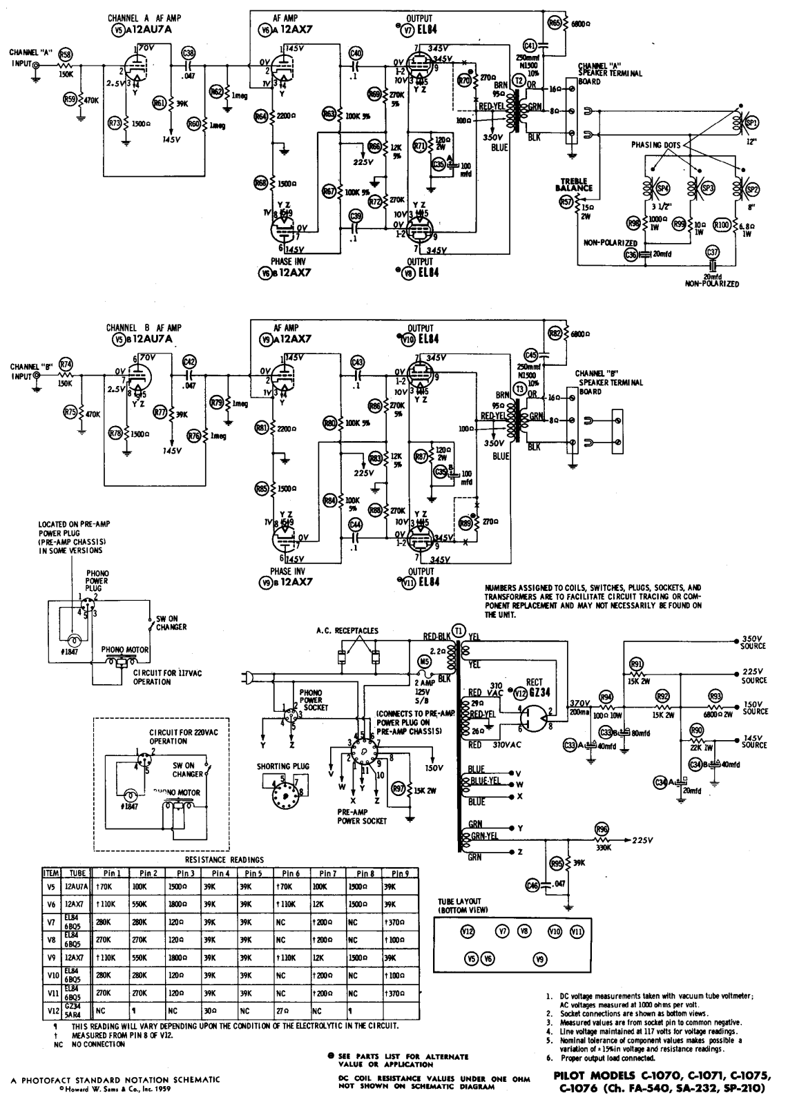
A search for a schematic diagram for the Pilot 505 amplifier has been conducted, but no results have been found. The amplifier utilizes five 5AR4 rectifier tubes, four EL84 power tubes, and two 12AX7 preamp tubes. Assistance in locating...
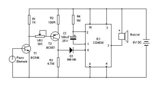
A vibration sensor or piezoelectric vibration sensor circuit diagram. It emits a loud beep when an attempt is made to break a door or window. The alarm automatically ceases after three minutes. The circuit utilizes a piezo element as...
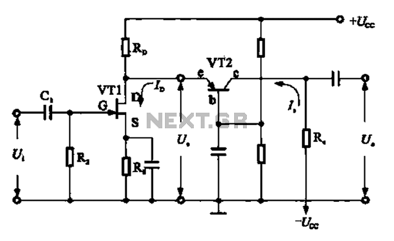
A combination of a common-source grounded base amplifier formed by cascaded amplifiers. The source is grounded, and a common base amplifier is combined into a cascaded amplifier. The graph below shows the low noise characteristics of the FET common-base...
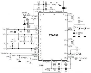
This is a stereo amplifier circuit diagram. The amplifier will produce stereo output channels with a power audio output that can reach up to 70W for each channel. The amplifier is built using the STA550 chip from STMicroelectronics. It...
Described timer to participate in the current circuit switch - bulb without any modification of existing pipelines. Connect the timer is in Figure 1 The time switch has only two outlets, which is connected in parallel to the button...

The sound produced imitates the rise and fall of an American police siren. When first switched on, the 10 µF capacitor is discharged, and both transistors are off. When the push button switch is pressed, the 10 µF capacitor...